• Steel Soldiers now has a few new forums, read more about it at: New Munitions Forums!

  • Microsoft MSN, Live, Hotmail, Outlook email users may not be receiving emails. We are working to resolve this issue. Please add support@steelsoldiers.com to your trusted contacts.


How to hookup MEP-802A and MEP-003A through Asco transfer switch to dual 200A panels

pclausen

Well-known member
Steel Soldiers Supporter
452
281
63
Location
Afton, VA
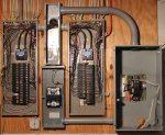
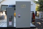
So I scored an Asco series 300 200A transfer switch on CL today for $300! These units normally run about $2000. I also picked up a 200A service disconnect breaker since the Asco is not Service Entrance rated.

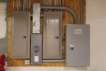
Here are a couple of pics of the pair:
asco300-01.jpg
http://www.cstone.net/~dk/asco300-01.JPG
asco300-02.jpg
http://www.cstone.net/~dk/asco300-02.JPG

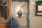
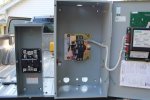
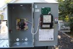
Some more pics of the Asco 300, which is virtually new looking!
asco300-03.jpg
http://www.cstone.net/~dk/asco300-03.JPG

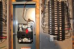
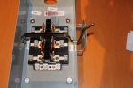
Closeup of actual transfer switch. Note the neutral connection bar on the left and ground connections on the right.
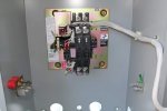
asco300-04.jpg
http://www.cstone.net/~dk/asco300-04.JPG

And the controller box.
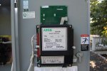
asco300-05.jpg
http://www.cstone.net/~dk/asco300-05.JPG

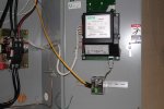
And with the cover off exposing the microprocessor. I plan to add the communications module, which will add an Ethernet port so that I can monitor/manage the switch from any computer with a web browser. It will allow me to monitor voltage and frequency of both the utility and generator sides.
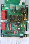
asco300-06.jpg
http://www.cstone.net/~dk/asco300-06.JPG

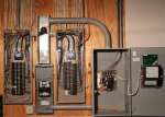
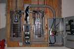
Got the service disconnect and transfer switch mounted next to my 200A panels. Note how the power from my 400A meter base comes in from the outside via that conduit in the middle of the picture and feeds each 200A panel.
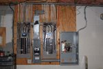
asco300-07.jpg
http://www.cstone.net/~dk/asco300-07.JPG

I have read the other threads here on how to ground everything to a single point and I *think* I got it right on the mock up wiring diagram below.

L1 - Red
L2 - Blue
Neutral - White
Ground - Green
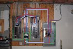
asco300-08.jpg
http://www.cstone.net/~dk/asco300-08.JPG

I'll be removing the grounding straps that currently bonds neutral and ground inside each 200A panel.

Also, I'll be running individual 3/0 copper from the Load terminals on the Asco transfers switch to each 200A panel. I'll need to trim the wire a little on the transfer switch end as 2 3/0 wires won't fit in the lug terminal. I know that I should technically be using a 400A transfer switch, but when I add up all the loads in the house, it comes in under 200A. The reason I got 2 200A panels is just due to the number of individual circuits. Water heater and stove are both propane. Heat pump is 20 seer with scroll compressor (Trane 4 ton XL20i just installed last year).

Should I for some reason draw over 200A, the service entrance breaker should trip I would think.

So outside I will have a MEP-802A which will be the primary generator and it will be connected to the Asco transfer switch by default via a 100A manual transfer switch. From that manual transfer switch, I'll be able to switch the emergency power over to a MEP-003A for the times that I'll need more than 5Kw of power (like when the aux heating elements come on during the winter and the heat pump goes into defrost cycle).

More to come.
 

pclausen

Well-known member
Steel Soldiers Supporter
452
281
63
Location
Afton, VA
Got the holes punched out and the conduits installed. 2 1/2" on top to carry 6 x 3/0 AWG and 2" on the bottom to carry 3 x 3/0 AWG.

xfer-9-27-01.jpg
http://www.cstone.net/~dk/xfer-9-27-01.JPG

I also got the house ground transferred from the main 200A panel to the service disconnect panel. It was a bit tricky as I had to run 2 temporary grounds to keep the whole house from being without ground during the transfer.

The red arrow shows the green neutral bonding screw I installed since this service disconnect box is going to the the grounding point for everything.

xfer-9-27-02.jpg
http://www.cstone.net/~dk/xfer-9-27-02.JPG

Next up will be rerouting the existing 3/0 wires and add new ones and then run the wires out to the generator pads with the 100A transfer switch between them.
 

bmwsyc

Member
80
0
6
Location
Brooklyn Center, MN
Do you plan on having the transfer switch start your generator(s)? There may be code issues if using an automatic transfer switch if your load is bigger than your alternate power source. I did read where you are using a manual transfer switch outside, but from what I understand, that will be used to switch between the 5k and 10k generator.

i also picked up a 100 amp transfer switch off of Craig's list, but sold it again because I thought a manual transfer switch allowed better code compliance and safety with a 002a and later my 10k EMU-10.
 
Last edited:

pclausen

Well-known member
Steel Soldiers Supporter
452
281
63
Location
Afton, VA
I plan to get an auto start kit for the 5KW MEP-802A and default the manual transfer switch to it. This way, when the power goes, the 802 will come online and feed both 200A panels. Based on some testing I have done, with everything in the house running, including the heat pump in 2nd stage of cooling, both panels combined pulls right around 20A @ 240V. The well pump did not run during that test, so that would be one scenario that the 802 might not like. I believe the Asco transfer switch will also allow load shedding, but I want to do some testing first to see what type of scenarios can/will make the 802 stumble.

I'm pretty sure the 003 will handle anything I throw at it, but fuel consumption and wet stacking are the drivers for having a smaller default generator, and only use the big guy during periods where I need to draw well in excess of 5kw, like during extreme cold weather when the aux heating elements need to kick on or during heat pump defrost cycles (which also kicks on the heating elements).

As long as both generators have breakers that will trip if they overload, why would there be code issues? The only code issue I can think of is that I'm using a 200A transfer switch instead of a 400A one since I'm feeding 2 200A panels, but as I stated before, there's no way I'd actually be able to pull even 200A, let alone 400A. Besides, the service disconnect breaker would trip at 200A, thus preventing damage to the 200A transfer switch, or anything else going bad. The Asco transfer switch also monitors the voltage and frequency of the power coming from the generator and will disconnect the generator if either voltage or frequency falls outside the range I specify over a set time period.
 
Last edited:

Isaac-1

Well-known member
1,970
48
48
Location
SW, Louisiana
There was a change to the NEC code in about 2006 that requires auto starting generators to be able to provide the full potential load that they are connected to, there is a list of allowable ways to determine what that full potential load is. Alternatively they must have load shedding capability. This revision to the code came about because so many big box store standby generators were being sold with whole home automatic transfer switches then being set up on homes that can at times draw more power than the generator could provide. Think all electric house with 2 4500 watt water heaters, electric oven that can draw another 5000+ watts, electric stove good for another 5000+ all before you get to air conditioner, etc. being connected to a 10-12KW residential standby generator with an output rating that was mostly optimistic thought on the part of the advertising department.
 

pclausen

Well-known member
Steel Soldiers Supporter
452
281
63
Location
Afton, VA
Ah yes, that makes sense. I can see why the code was changed. Back on 2012 when we had the derecho storm, we had no power for a week. My folks had a 15kw Generac standby generator, and it would trip when the water heater came at the same time the oven was running and the A/C (old inefficient unit). Not only that, but it the engine failed on day 4 since those Generac Guardians are not continuous duty. I had a 8kw Generac during the derecho and had to be very careful about what I was running and shut it down when it was not needed. A/C was out and the house was hot as ****, and my wife was pregnant at the time. It was not a fun week.... Around my parts we loose power for at least 24 hours in any given year, and lately the average seems to be more like 3+ days.
 

pclausen

Well-known member
Steel Soldiers Supporter
452
281
63
Location
Afton, VA
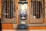
Completed the #4 ground wire connections to both 200A panels and the transfer switch.

xfer-9-29-01.jpg
http://www.cstone.net/~dk/xfer-9-29-01.JPG

Closeup showing the 4 #4 runs from the service disconnect breaker.

xfer-9-29-02.jpg
http://www.cstone.net/~dk/xfer-9-29-02.JPG

I also completed the 4-wire run from the generator pad area into the transfer switch. L1, L2 and N are all #4 wires. GND is #6 or #8.

The high voltage cable is run in a separate conduit from the low voltage control cable to control starting and stopping the generator.

xfer-9-29-03.jpg
http://www.cstone.net/~dk/xfer-9-29-03.JPG

Now I'm just waiting for 3 of these to show up so that I can properly split the load side from the transfer switch between the 2 panels.

http://www.cesco.com/b2c/product/45...1_a_7c451767&gclid=CLaAwZKNh8ECFenm7AodWkAAHQ

Picked them up on eBay for 11 bucks a piece.

Here's the outside mounted 100A transfer switch that I ordered. Seem to be relative bargain for $118 with free shipping.

http://www.homedepot.com/p/GE-100-A...ency-Power-Transfer-Switch-TC10323R/100171587
 
Last edited:

tim292stro

Well-known member
2,118
39
48
Location
S.F. Bay Area/California
I think you need an MEP-005 or MEP-805... 200 Amp service is about 24kW.

Is one of those two 100Amp panels an "emergency loads" panel? Are you planning on "teaming" the 802/003?

I hate to ask, but did you get a permit to do this work?
 
Last edited:

pclausen

Well-known member
Steel Soldiers Supporter
452
281
63
Location
Afton, VA
You're right that 200 Amp service is about 24kW. I actually have 400 Amp service, so that would be about 48kW. :shock::shock::shock:

The thing is, however, that I would never come close to drawing that much. My water heater is propane, as is my cook top and oven. A/C is very high efficiency (20 SEER), installed just least year, all my light bulbs are LED, so even if I tried, I'd never be able to draw 200 Amp, let alone 400. I got 400 Amp service because I, in theory, could draw 400 Amp if I had circuits within each 200 Amp panel that would add up to that much, but I don't.

Both 200 Amp panels will be powered from the single 200 Amp transfer switch so that *ALL* the circuits in the house will be on emergency power when I loose the mains. Under *MOST* circumstances, the lovely little 5KW 802 should be able to handle the load. For the times when it won't be enough, I'll manually switch over to the 003. The only time I envision this being necessary would be when loosing power when it is below freezing outside as that will require the heat pump to go into defrost mode every now and again, which will bring the resistive heating elements.

I thought about merging all the circuits that needed emergency power into a single 200A panel, but they would just not fit. I also considered having the 802 power one panel and the 003 the other, but that would not work out because that would have meant the heat pump would have to be wired to the 003 at all times, and 99% of the time, the 802 would be sufficient to power it.

Down the road I plan to replace the 003 with a 803. It's too bad you have to jump to the 15KW 804 before they come with built in load sharing. From what I've read, it is next to impossible to sync a pair of 802s or 803s since the voltage regulators can't be configured as master and slave.

I did not get a permit even though I realize that technically I should have.
 
Last edited:

tim292stro

Well-known member
2,118
39
48
Location
S.F. Bay Area/California
...I did not get a permit even though I realize that technically I should have...
Forgive me if I edit the sentence in the interest of being honest with yourself: "...I did not get a permit even though I realize that {REMOVED} I should have..." And that little voice in your head that types out as doubt means you know it. :)

The point of the NEC discussion above is that you CAN overload your setup (tripping the generator's breaker) with your configuration - and it's not so much "you" as any potential future home owner (even if this is your 15+ year house, some day it won't be your house). I have to recommend that you get a permit, and you're going to have to fix stuff that isn't to code. I implied an easy fix, a sub panel with your emergency loads, if you can't parallel your generators to take the full house load. Hearing that you have 400Amp service just makes it that harder to "whole house" your back-up system and be legal.

You aren't feeding a 200 Amp transfer switch 400Amp service are you? It's breakered to 200Amps right? Even if you have feed wires and an upstream transformer that can provide 400Amps, if it's breakered for 200Amps, you have 200Amp service.

Remember that the military hardware will try its darndest to run whatever you throw at it - in combat you want to do a job that you need to do, and that may mean that you intentionally ruin a piece of hardware because it makes sense for the situation - that capability doesn't go away when a DoD genset is purchased from GL (et al), so you need to understand what conditions your equipment will protect itself, and which it won't. If I remember my MEP's correctly, there is a user accessible way to over-ride the generator self-preservation logic - if you want to rely on the generator protecting itself, you need to make sure it cannot decide not to.

Don't think I'm being discouraging either, I am all about over building the h3l1 out of stuff, but I try to do it smart. And what I mean there is, really take a moment to think about what you'd want to run in a power outage. You have two gen sizes, and for your average household they would make a good split between short and long outage:
  • For a short outage think about safety, and basic comfort - you and your family can probably handle whipping out the candles and having a nice dinner with a glass of whatever adult beverage you prefer (i.e. the power outage is still "fun")
  • For a long outage think about mitigating damage to your property, and more advanced comfort - sitting in sweat-soup for a week, and losing a refrigerator full of food, and not being able to do laundry would cause spousal strife - and I'm sure there would be some words about "how your hobby isn't doing anything for the family..." - sounds like I've heard something similar before right? (i.e. "now we are genuinely worried about how long this is running and we are leaning more towards survival").

Two emergency breaker panels would do the trick
  1. A 30amp panel attached to the MEP-802 and giving you basic exterior/interior lighting, garage door access, bathroom vent fans, running the refrigerator (optional if you think you can remember to keep it closed), maybe some basic entertainment (PC, TV...).
  2. An 80Amp panel attached to the MEP-003 (803 later) giving you more long term comfort - more lights, HVAC, laundry, and on and on...


If you can't or won't do the emergency panels to the rating of the generators (remember to reserve ~20% capacity for code), then as previously stated you'd need to do an energy management system - this would mean using breakers that can be controlled remotely to shed loads that the available generation could not support. The good news is that this can be pretty simple if you know how - most EMS breakers are 24Volts, which can be controlled from a transfer switch, if the power service fails it dumps the loads that don't run on the generator immediately. This way, when the generator comes up, it can't be over-loaded as the transfer switch ticks over to emergency power. The loads are only reconnected upon satisfaction of three conditions:
  1. Power Service restored
  2. Transfer switch flipped back to Power Service supply (not generator)
  3. Power Service is stable for a time-out period

Looking at the way you decided to wire up your panels, I think this would be harder to do - the ASCO 300 is only designed to control one down stream load group, you have two possible generation points on your system, and they (by your own admission/understanding) can't supply the load simultaneously. Is your feed from the two generators separated by another DPDT switch? The only other way to do the EMS solution is to have two of the ASCO transfer switches.

To be code compliant you basically can't have a system design where it's possible, for someone not trained thoroughly on your system (and that will be everyone but you), to do something stupid. If you remember the phrase "idiot proof" and the counter "everytime we make this idiot proof, they go an make a better idiot" - it just means you were designing to the wrong target. To h3ck with the idiots, make it failsafe.

It'll take a bit more thought, but you'll feel better about the outcome, and you'll be more likely to pass an inspection after the permit is obtained.

Cheers! :beer:
 
Last edited:

lxawolf

Member
44
1
6
Location
Sussex, NJ
I think you need an MEP-005 or MEP-805... 200 Amp service is about 24kW.

Is one of those two 100Amp panels an "emergency loads" panel? Are you planning on "teaming" the 802/003?

I hate to ask, but did you get a permit to do this work?
Not to jump into anything one way or another but 200amp at 240 volt is actually 48KW so 400 amp at 240 volts would be 96KW. Amp X Volt = Watt.
 

pclausen

Well-known member
Steel Soldiers Supporter
452
281
63
Location
Afton, VA
Hi Tim,

I appreciate your feedback and you are correct that I'd be the only one that would capable of running the system once I'm done. I have owned/lived in this house for the last 15 years, and plan to be here for another 30 (I hope). That said, you are absolutely correct that one day someone else will be in the house. Before that time, I plan to have either upgraded the system I'm currently contemplating, or remove it if I move out for some reason.

And you are correct that I really have a 200A service now since the 400A service from the pole is going through the 200A service disconnect breaker, so this prevents me (or anyone else) from overloading the transfer switch past it's 200A rating.

And yes, the feed from the 2 generators is separated by another DPDT switch (a 100A manual transfer switch). In fact, it just showed up, here's a pic of it:

100Axfer.jpg
http://www.cstone.net/~dk/100Axfer.JPG

Prior to my current setup, I had a 100A sub panel and a 15KW Generac generator with a 100A automatic transfer switch. That setup was ok, but the 100A sub panel did not have enough positions for all the circuits I wanted. So this time around, I wanted to just power all panels from a single emergency power source, and that source could be scaled to the load at hand.

I do plan to add load shedding relays. For example, the well pump will be off when the HVAC is using any heating elements and visa versa. Likewise, the dryer will be off at all times when on emergency power. Those 3 are the only power hogs in my house.

Again, I appreciate the advice and concern and you definitely bring up a good point about the scenario where someone else would attempt to run the system. I'll endeavor to make is as fool proof and save as possible. Might even go ahead and get an inspector to look at it, but I'll need to make some changes since I know he won't pass it with a 200A transfer switch feeding 2 200A panel, even with the 200A service disconnect in front of it. And that's before even starting to talk about the generator ratings.
 

tim292stro

Well-known member
2,118
39
48
Location
S.F. Bay Area/California
I'll endeavor to make is as fool proof and save as possible.
Not fool proof, fail-safe :)

...the feed from the 2 generators is separated by another DPDT switch (a 100A manual transfer switch)...
Ah, I missed that in you earlier post, now that you mention it I see you had said that.

...he won't pass it with a 200A transfer switch feeding 2 200A panel, even with the 200A service disconnect in front of it....
I don't think that would be an issue, I'm not aware of any code where you aren't allowed to use a panel or combination of sub panels that is rated higher than the service+protection provided to it, the issue comes if you put something like a 150Amp panel behind a 200Amp breaker (instant fail). The reason most don't over-do the downstream ratings is cost $$$.

...For example, the well pump will be off when the HVAC is using any heating elements and visa versa. Likewise, the dryer will be off at all times when on emergency power. Those 3 are the only power hogs in my house...
So, a suggestion - if you have three "big loads" and a butt-load of other loads which are smaller, why not split the generator power out that way? I'm just thinking of ways you can cut costs, and make the system more manageable...

Cheers! :beer:
 

pclausen

Well-known member
Steel Soldiers Supporter
452
281
63
Location
Afton, VA
The thing is that by putting the well pump and HVAC on the large generator, I'd need to fire that up anytime I needed water or heating or cooling. That just seems like a hassle when the small generator is likely able to handle both of those loads (and the small ones) 95% of the time.

I'll know a lot more once I actually test all this out for real and will make adjustments as needed. Yes, fail-safe is what we want. :)

Also keep in mind that the Asco is constantly monitoring the power coming from the generator and will drop it if the voltage or frequency falls outside safe levels. This is in addition to the breaker on each generator. Anyway, I'll know a lot more once I get it up and running and run some controlled tests.

I picked up the 003 and 2 more 802s today. So I'm getting closer to being able to begin testing!

MEP-003A-01.jpg
http://www.cstone.net/~dk/MEP-003A-01.JPG
 

pclausen

Well-known member
Steel Soldiers Supporter
452
281
63
Location
Afton, VA
Got the 200A transfer switch cut in today. It was a pain dealing with that thick 200 AMP copper wire for sure!

First I pulled out the 6 existing pieces. Sorry these first few pics are crappy cell phone pics as I was in a hurry to get power restored.

Inside looking out:

xfer-10-6-01.jpg

Outside looking in through the meter base:

xfer-10-6-02.jpg

The 6 pieces of cable I pulled. Fortunately I was able to reuse all but a foot or so.

xfer-10-6-03.jpg

And here's a shot with all the new cable pulled and connected inside and out. Power has been restored at this point and everything is working properly. The last step before restoring power was to remove the grounding bonds in both 200 A panels.

xfer-10-6-04.jpg
http://www.cstone.net/~dk/xfer-10-6-04.JPG

And a shot with all the covers back in place:

xfer-10-6-05.jpg
http://www.cstone.net/~dk/xfer-10-6-05.JPG

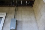
Also got the conduit run to the outdoor manual 100 A transfer switch:

xfer-10-6-06.jpg
http://www.cstone.net/~dk/xfer-10-6-06.JPG

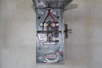
Inside switch. Low voltage control wires are just coiled in here for the time being.

xfer-10-6-07.jpg
http://www.cstone.net/~dk/xfer-10-6-07.JPG

Picked up oil, filters and batteries for the 003 today as well. So I hope to get it up and running and wired in by the weekend.
 
Last edited:

pclausen

Well-known member
Steel Soldiers Supporter
452
281
63
Location
Afton, VA
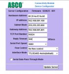
Got my Ethernet Connectivity Module today and got the DIN rail installed and the module. I connected the serial cable (which provides power to the module) as well and the Ethernet cable going to my switch. I even installed a ferrite bead onto the Cat 5 cable where it entered the Module for good measure. Trying to do everything by the book. :)

asco-10-10-01.jpg
http://www.cstone.net/~dk/asco-10-10-01.JPG

After changing a workstation on the LAN to be on the same subnet as the Asco Connectivity Module default IP address, I was able to connect to it and change the IP to my subnet, reboot and connect.

asco-10-10-02.JPG

But, when I then attempt to connect to the actual control module of the transfer switch, I get this error:

asco-10-10-03.jpg

So I'm kinda bummed right now. I have tried different baud rates and rebooted both the Connectivity Module and the transfer switch controller (which unfortunately meant taking the house off-line for a few minutes) to no avail.

Don't know if any of you guys have any experience with these transfer switches? I guess I'll call Asco support on Monday and see if we can figure this out. Spoke to them today and was impressed with the support I received. I was verifying the pin out of the DB9 serial cable between the communication module and the controller.
 
Last edited:

pclausen

Well-known member
Steel Soldiers Supporter
452
281
63
Location
Afton, VA
I have tried firefox as well, made no difference. I had to go into the Java Control Panel and make a security exception for the url of the communication module before either browser would even communicate with the unit, due to how old the Java code is that runs on the controller. The user guide is from 2004 and talks about how to make a connecting using Internet Explorer 5.0 under Windows 2000. :)

The issue appears to be the communications over the RS-232 serial ports between the control module and communications module. I'll try another serial cable and also ohm out each wire to make sure they are all good.
 

m-35tom

Well-known member
Supporting Vendor
3,020
220
63
Location
eldersburg maryland
sounds like they need to issue a upgrade to their software. i have a old best power ups and have never been able to get it to communicate which is the only way to check on much of it's functions.
 
Top
AdBlock Detected

We get it, advertisements are annoying!

Sure, ad-blocking software does a great job at blocking ads, but it also blocks useful features of our website like our supporting vendors. Their ads help keep Steel Soldiers going. Please consider disabling your ad blockers for the site. Thanks!

I've Disabled AdBlock
No Thanks