• Steel Soldiers now has a few new forums, read more about it at: New Munitions Forums!

  • Microsoft MSN, Live, Hotmail, Outlook email users may not be receiving emails. We are working to resolve this issue. Please add support@steelsoldiers.com to your trusted contacts.


MX-7777 suppressor help needed

Steamynachos

Member
178
3
18
Location
Calgary Alberta
Hi guys I am getting a mx-7777 suppressor from a guy and want to install my Prc-77 in my truck now I dont know the first thing about the suppressor and cant seem to find anything on the net about it. What is the power cable from the battery to the unit number will a CX-13089 work? what plug does the radio tray plug into is it the little plug in the back of the unit? Any help would be great Thanks
 

BillIdaho

Member
417
7
18
Location
Caldwell, Idaho
Punch in "VIC-1" in the search mode..... then click on the second or third one down. Towards the bottom of that posting someone, ( to whom I owe great thanks for the help it gave me!) posted a schematic of the VIC-1 system, BUT it includes all the cables numbers and where they go for your needs. It has the routing for cables from the batteries to the MX-7777, to the VIC-1 system (if you need that info) to the RT, to the antenna, etc. Best schematic I have seen in a long time. Basic, but complete.
 

ONTOS66

Member
433
3
18
Location
Franklin, NJ
Check Technical Manuals under Resources. I'm uploading the following:

TM 11-5915-223-12, Operator & Organizational Maintenance, MX-7778/GRC
TM 11-5915-224-14, Opeartor & Organizational Maintenance, MX-7778A/GRC

I also have the other manuals for this equipment if anyone is interested in having them uploaded.
 

OPCOM

Moderator
Steel Soldiers Supporter
3,657
27
48
Location
Dallas, Texas
It's very interesting. Thanks!

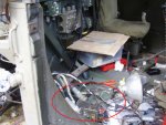
Looks like a very big 33V Zener diode, a thermal switch that closes when the chassis reaches a certain temperature, and an electronic temperature sensor that closes when the Zener diode reaches a certain temperature. There is a large 2-pole circuit breaker. The sensors trip the circuit breaker and remove power from the diode and the output when the temperature becomes excessive. I think the breaker has a high-current pole for the power through the unit, and a lower-current pole to be tripped by the temperature switch or sensor. (Mine is partly disassembled, will have to look later, maybe Bjorn may remember, since he has had them apart also.) The breaker poles are mechanically ganged so tripping one side trips the other. Unfortunately the part details are somewhat vague. - but this can definitely be repaired if broken, so that at least the spike/transient protection is retained.

One thing I noticed in the -14 manual in the test section, figure 6-1 / table 6-3 is that they say to use two 10 ohm 10 watt resistors. One is in series with the power supply, and the other is across the output of the supressor.

The test is designed to determine if the Zener diode is able to limit the voltage to 33-36 volts.

I think the test procedure is mistaken and could present a small safety hazard. The resistor at the supresor output is going to get mighty hot if it has 33-36 volts across it.

-But assuming the power supply is set to 38V, the entire circuit as shown is essentially two 10 ohm resistors in series with the zener diode connected from the point in the center of the resistors to ground. With 38V across the resistor chain, the voltage across each resistor, and across the zener diode would be only 19 volts and it would not conduct. Each 10 ohm 10 watt resistor would have 19 volts across it and dissipate (19/10)*19, or 36.1 watts. (overload).

I believe the proper way to test it would be to not use the 10 ohm resistor shown at the output. Then, with 38 volts from the supply, the first 10 ohm resistor will limit the current to the zener diode because the zener diode will have enough voltage to conduct and the voltage would read the 33 to 36 volts.

I could be completely mistaken or mis-read the instructions, been wrong before, but to try to explain my point on the test, please see the schematic below. I'd welcome comments or corrections on this.
 

Attachments

ONTOS66

Member
433
3
18
Location
Franklin, NJ
If anyone in the group is interested I also have the following available in .pdf:

TM 11-5915-223-12-HR
TM 11-5915-223-24P
TM 11-5915-224-24P

Let me know if anyone is interested and I'll upload them (and hopefully the web folk will have that problem of opening documents solved by then)
 

ONTOS66

Member
433
3
18
Location
Franklin, NJ
OPCOM, The -24's are up in the Reference section in case you hadn't found them already. When you mounted your MX-7778 what did you mount it to? Directly to the floor? Or some sort of shock mount? I was thinking of something in the way of a dense rubber pad since I can't seem to find the correct mounting feet (I'm sure that there are cases of them sitting out in the rain somewhere)

;)
 

OPCOM

Moderator
Steel Soldiers Supporter
3,657
27
48
Location
Dallas, Texas
I have not yet mounted it, however, it should be mointed to some metal surface like a cab wall or floor or other bulkhead etc. so that it can dissipate any heat. It is not likely to do so for normal operation, but in case the voltage should rise above the Zener diode's threshold, it could become very warm. It must not be allowed to be over 100 deg C while shunting current (you may wish to research zener diodes with a 33V / 300 watt rating). The thermal sensing devices are designed to trip the circuit breaker in event of temperature overload. As for weather, if the seal is good on the box and connectors, it is rain-proof. I do not believe it is submersible. No shock mounting is necessary.
 
Top
AdBlock Detected

We get it, advertisements are annoying!

Sure, ad-blocking software does a great job at blocking ads, but it also blocks useful features of our website like our supporting vendors. Their ads help keep Steel Soldiers going. Please consider disabling your ad blockers for the site. Thanks!

I've Disabled AdBlock
No Thanks