• Steel Soldiers now has a few new forums, read more about it at: New Munitions Forums!

  • Microsoft MSN, Live, Hotmail, Outlook email users may not be receiving emails. We are working to resolve this issue. Please add support@steelsoldiers.com to your trusted contacts.


MEP-803a voltage drop during monthly test

nextalcupfan

Well-known member
348
506
93
Location
NW Missouri
Fired up my 803a for its monthly test run, noticed my UPS hooked to my computer was showing an input voltage of 111-113V.
Last month it was around 119-121V.
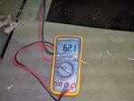
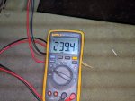
I got my Fluke 17B out to confirm and L1-L3 was reading 231V. (When I last set it earlier this year I put it at 244V)

I was able to adjust it back up to where L1-L3 was at 241V but I noticed 2 things.
1. The voltage adjust potentiometer is almost maxed out.
2. When I was adjusting it it didn't seem to be acting right. The first thing I did was turn the knob down and the voltage went up by 0.5V before it started going down.
I also noticed the voltage seems to be ranging a bit more than usual (+-2V)

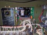
Going to figure out what TM the regulator test procedure is in and run that test sometime tonight, but I have a feeling its the probably the potentiometer going bad.
I should note I've sprayed it with Deoxit in the past as a preventative measure.

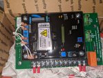
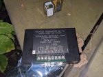
To be honest I'm probably going to just replace the entire VR with one of @kloppk 's units since I've been considering doing that anyway.
 

nextalcupfan

Well-known member
348
506
93
Location
NW Missouri
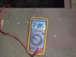
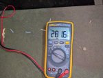
I did a quick range test for Min/Max Voltage.
First the Knob Position for 240V.
Voltage 240 Knob Position.jpg

Min Voltage
Voltage Min 1.jpg

Max Voltage (I should note here the voltage stops going up with the knob at around the 4 o'clock position)
Voltage Max 1.jpg

I found if I wiggled the knob at minimum value the voltage would fluctuate
Voltage Min 2.jpg

According to the TM the voltage adjustment range in 120/240V mode should be 228-252V
 

Ray70

Well-known member
2,373
5,073
113
Location
West greenwich/RI
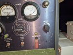
I see the Hz gage is pegged up on 65 Hz, is it malfunctioning or is the gen running excessively fast?
It does sound like the external potentiometer is either dirty or going bad.
At first that non-standard AC volt gage along with the L3-N AM/VM switch setting and 240V reading on your DMM really threw me for a loop until I looked closer and saw the 100-300V scale on the bottom of the gage!
 

nextalcupfan

Well-known member
348
506
93
Location
NW Missouri
The Hz gauge is off by about 1.5.
At the time I took the pic it was probably around 62Hz.

This spring I did a governor droop adjustment.
It should be 61.8 at 0 and 60.0 at 100%

Right now at 75% it was running 60.5hz
 

Light in the Dark

Well-known member
Steel Soldiers Supporter
3,574
5,111
113
Location
MA
Have you tried to adjust the gauge with the small panel fitting at the center, with a screw driver? You might be able to bring the hertz gauge back to reading correctly.
 

Scoobyshep

Well-known member
914
989
93
Location
Florida
One thing I have done to pots when they act funny, with the set off crank the pot all the way up and back down several times. sometimes the wiper gets corroded and needs a degunking. If its an open pot (you can see the wiper) a little deoxit goes a long way
 

nextalcupfan

Well-known member
348
506
93
Location
NW Missouri
Have you tried to adjust the gauge with the small panel fitting at the center, with a screw driver? You might be able to bring the hertz gauge back to reading correctly.
Yea I tried that, the closest I could get was 0.6Hz above what it was running.
So I decided to adjust it so it was exactly 1Hz above what it was reading.

Any suggestions on a replacement unit? that doesn't cost me a kidney.
I would prefer not getting one of those super cheap Chinese ones but at this rate I might as well. While I don't like them I do believe they are fairly accurate which would be good enough for my use.
 

nextalcupfan

Well-known member
348
506
93
Location
NW Missouri
One thing I have done to pots when they act funny, with the set off crank the pot all the way up and back down several times. sometimes the wiper gets corroded and needs a degunking. If its an open pot (you can see the wiper) a little deoxit goes a long way
I did try going back and forth yesterday, all that accomplished was I figured out if I wiggled it at minimum the voltage would fluctuate.
Like I said I sprayed it with Deoxit sometime last year? maybe the year before.
Since COVID everything has mushed together in my head.
 

Light in the Dark

Well-known member
Steel Soldiers Supporter
3,574
5,111
113
Location
MA
I have one here to be tested out of a machine. They aren't cheap, thats for certain. Don't actually see a mil spec one for sale anywhere at the moment.
 

nextalcupfan

Well-known member
348
506
93
Location
NW Missouri
Quick question, been reading the TM on the potentiometer check procedure and it wants me to desolder the 3 connections on the back.
For just checking it couldn't I just disconnect the wires from the VR?

It looks like terminals 1 and 2 on the VR and a wire is looped around from R to C on the potentiometer itself.

So I could probably disconnect wires 1 and 2 from the VR and desolder the center wire on the potentiometer?
 

kloppk

Well-known member
Steel Soldiers Supporter
1,962
3,054
113
Location
Pepperell, Massachusetts
No need to unsolder any wires.
Just remove the wires attached to VR terminals 1 & 2.
Then measure the resistance between the two wires as you rotate the voltage adjust. Should go from about 0 ohms to 5,000 ohms smoothly.
 

nextalcupfan

Well-known member
348
506
93
Location
NW Missouri
No need to unsolder any wires.
Just remove the wires attached to VR terminals 1 & 2.
Then measure the resistance between the two wires as you rotate the voltage adjust. Should go from about 0 ohms to 5,000 ohms smoothly.
I kind of figured that would be enough, but the TM wants to check between the 2 outer terminals to see if it has 5k ohms.
If I wanted to follow the procedure to the letter I'd have to desolder the center terminal to check that.

But to be honest I'm pretty terrible at soldering so I may just go with Kurts plan here, also I would only have to bring a screwdriver and multimeter down to the generator instead of my whole soldering kit.
 

nextalcupfan

Well-known member
348
506
93
Location
NW Missouri
I just ran the test and got 40-4.5k ohms with some very minor fluctuations on the way up.
I also noticed I could go past 4.5k ohms on the knob but the reading wouldn't change.

because a video is worth a thousand words here you go
 

peapvp

Well-known member
Steel Soldiers Supporter
1,032
1,055
113
Location
Basehor, KS
I just ran the test and got 40-4.5k ohms with some very minor fluctuations on the way up.
I also noticed I could go past 4.5k ohms on the knob but the reading wouldn't change.

because a video is worth a thousand words here you go
the rheostat is worn out and past it’s prime. I would get a new one.
 

kloppk

Well-known member
Steel Soldiers Supporter
1,962
3,054
113
Location
Pepperell, Massachusetts
Yes, the higher than voltage range is there so that users can use the generator to power applications that require higher voltage than the nominal 120/240/208.
Had received several requests early on for that specific capability.
This can be done as long as one doesn't exceed the overvoltage threshold of the set.
 
Last edited:
Top
AdBlock Detected

We get it, advertisements are annoying!

Sure, ad-blocking software does a great job at blocking ads, but it also blocks useful features of our website like our supporting vendors. Their ads help keep Steel Soldiers going. Please consider disabling your ad blockers for the site. Thanks!

I've Disabled AdBlock
No Thanks