• Steel Soldiers now has a few new forums, read more about it at: New Munitions Forums!

  • Microsoft MSN, Live, Hotmail, Outlook email users may not be receiving emails. We are working to resolve this issue. Please add support@steelsoldiers.com to your trusted contacts.


gauge cluster conversion question

richingalveston

Well-known member
1,715
120
63
Location
galveston/Texas
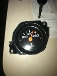
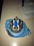
I think our pin out documentation is the same. I currently have everything working except the water temp gauge. I installed a single wire sending unit and I cannot get the gauge to move, it just stays on cold. I am going to change to the 2 wire sending unit which is grounded at the sending thus eliminating a lot of resistance in the loop caused by using the ground in behind the dash. The two wire unit since has a direct wire to the sending unit for the ground which lowers the resistance read by the gauge. I purchase the new sending unit today and plan to get it changed this weekend.
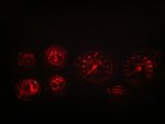
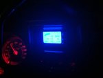
I am keeping the idiot light sending units and have combined them to light the check engine light and have added the gauge sending units for the oil pressure and water temp. once I get the temp gauge working I can put the dash back togather and work on other stuff.
 

dyocis

New member
85
0
0
Location
Paso Robles, CA
I used the part numbers you posted for the sending units, but I'm not 100% sure that my temp gauge is working either. It does move very slightly if I let the truck run for a couple of minutes, but my mechanic is still working on the engine, and other things and doesn't want to keep the truck running for too long so its hard to be sure the gauge is working as it should, but I know it moves. Once I can let it run for about 1/2 an hour or so I should know better.
 

richingalveston

Well-known member
1,715
120
63
Location
galveston/Texas
I will check the two wire sending unit tomorrow, it is more expensive because you have to buy the plug also. If it works I will post the part numbers. I think the sending unit and plug was around $45. which is three times the cost of the single wire sending unit.
 

richingalveston

Well-known member
1,715
120
63
Location
galveston/Texas
does anyone know how to wire this water temp gauge. This was in the civy cluster that I pulled from the 87 suburban with 350 gas motor that I parted out. I have been able to get everything working but this gauge. oil pressure gauge works, fuel gauge works, tach works. The water temp gauge does not. It is in the same location and using the same pins that were used on the 350 chevy. I also purchased a new gauge and got the same results with the new gauge. Looking at it from the back, the top pin (silver) is the 12volt input, the left pin is the ground and the right pin is the sensor input. the bottom pin did not connect to anything. I have tried two different sending units, one is the single pin conector and the other is a two wire connector with new plug. When using the single wire, I wired the ground to the small ground terminal behind the dash and when using the two pin I ran a second wire from the sending unit to the ground terminal on the gauge. the gauge needle stays all the way to the left and does not move no matter what the engine temp is. I can check the OHM readings at the sending units and It does change as the engine temp changes so it appears the sending unit is working. I checked the terminals in the cluster and could read power on the top pin and I could read the ohms changing with engine temp. The gauge worked when in the suburban before I parted it out. I am not sure what else to do to make it work. I have not tried to connect anything to the bottom pin because I dont want to burn up the gauge but maybe this pin needs to be grounded. Not sure, if anyone has any experience with this temp guage please let me know what I might be doing wrong.
Thanks,
 

Attachments

cpf240

Active member
1,479
5
38
Location
Free in Northern Idaho
If it were me, I'd be assuming that the top and bottom terminals, with the white part between them, would be the 12v and the signal wires. It looks just like the back of the CUCV voltmeter to me, with a resistor and everything. I'd expect the other two threaded posts were for mounting, though they may very well be grounded to the case.

Try making some measurements with an ohm meter across the various terminals while the gauge is on the bench and see what you get. I'd expect some resistance between the two terminals with the nuts on them in your picture, and probably nothing between either threaded post and the terminals with the nuts.

Just my guess though...
 

richingalveston

Well-known member
1,715
120
63
Location
galveston/Texas
finally got he temp gauge working. the top teminal is the ground. the left terminal when looking at the back is power and the right is signal. The single wire sending unit works. I had a bunch of issues from bad ground to broken signal wire. The signal wire had a bad spot in it that I did not see when installing.
without the signal wire problem and the ground issue the gauge would have worked the first time. All is good now, I can put the dash back togather. I also got some larger/brighter led's for the left side of the gauge cluster so it is as bright as the right side. I also got the led bulb for th volt meter it works but a little dim.
The 87 burb cluster is installed and all gauges work. I now have to figure out how to adjust the back up lights. since I changed the column to the tilt and put the 4l80e in, the reverse lights now come on when in neutral instead of reverse.
 

richingalveston

Well-known member
1,715
120
63
Location
galveston/Texas
red led dash

here is a pic of the red led dash, it is very easy on the eyes the bulbs do not dim but it is not needed with the red. I also put led's in the tail lights and marker lights. All lights in the rear are led including the reverse lights, the front side markers are led but in order to make the flasher work, the front amber bulbs under the headlights had to remain regular bulbs.
the rear tail lights are about 25% brighter. did not get pictures of the rear taillights will get bulb info posted soon for others.
 

Attachments

richingalveston

Well-known member
1,715
120
63
Location
galveston/Texas
civy cluster install, finished with trans controler

I finished the civy gauge cluster install. All gauges work, I also installed the TCI trans controler behind the dash in the stock volt meter location. I removed the black bracket holding the voltmeter (voltmeter on far left side of cluster now)and built a custom bracket to hold the trans computer. I installed a power switch in the black plastic on the side of the trans controler. Attached is a pic of the trans controler and tach, The tans controler has a tach read out along with speed read out. The speed is calculated from the transmision rpm and you program your tire size and diff ratio so it will be pretty accurate. I am trying to post a video of the working cluster with engine running but for some reason I cannot get it to upload.
 

Attachments

ssdvc

Well-known member
971
639
93
Location
CT
Awesome project Rich. Could you post all part numbers and sources used so we can copy your efforts?

Thanks !
 

richingalveston

Well-known member
1,715
120
63
Location
galveston/Texas
I don't know all of the part numbers but sometime this weekend I will get the ones that I know.
It is a civy cluster from an 87 suburban. It came with large fuel gauge, speedometer with trip odometer, temp gauge,12 volt meter, oil presure gauge and had one emty hole.
I purchased the small fuel gauge and the tach from LMC. I removed the existing 12 volt meter, cut out the housing and moved the standard cucv volt gauge to this hole and I put the small fuel gauge in the existing empty hole.
The fuel gauge, tach, and 24volt meter all have new wires to them and do not use the existing circuit board. I also ran seperate wires for the gen 1 and gen 2 lights which were moved to the bottom of the tach. In the bottom of the speedo I have a check engine and the 4x4 light.
The check engine uses the old sending units that were for the oil presure, water temp and low coolant lights, Any of the three sending units will light the check engine light. I installed splitters on the sending unit locations with small brass fittings so that I could install two sending units, one for the light and one that works the guage.
I used two different types of red Led's some brighter than others so that I could get the light as even as possible in the cluster. The Led's do not dim so but they really do not need to with the red lights. It is very easy on the eyes at night. I beleive I can dim the trans controler light some but have not adjusted the settings yet.
I will get some daylight pics of the dash and post it also. You can see that the trans controler has a tach display along with a MPH display.
If you want to know what a lot of insulation to your CUCV can do, listen to the motor in the video, I am running the truck inside the barn with the all of the barn doors closed and with the truck doors closed. Inside the truck, it is as quieter than the ford powerstroke (07) my dad drives and it is as quiet as the duramax (05) I drive.
 

richingalveston

Well-known member
1,715
120
63
Location
galveston/Texas
that spread sheet may not be correct. I think it had a mistake that did not get corrected and I do not remember what was wrong. it is close but I believe a couple wires are mixed up.
 

Barrman

Well-known member
5,153
1,555
113
Location
Giddings, Texas
Since this has become the gauge update/wiring thread of choice now. I will chime in what I have figured out recently.

I thought after following this thread when it was new and looking at parts suppliers like LMC that there were 3 different printed circuit mats for the gauge clusters. Nope, there are several more.

The CUCV pc mat is unique to the CUCV. Which means the big plug is also unique.

Gas powered idiot light square body trucks newer than 1981 had another pc mat.

Diesel powered idiot light square body trucks newer than 1981 had yet a different one.

Gas gauge trucks are different than all the above. Diesel gauge trucks are different than gas gauge trucks.

The 4x4 light got moved around some as well in different years and versions. The little clock threw another twist into the mix as well.

I learned all of this the hard way. I have around a dozen CUCV clusters, 5 or so gas gauge clusters and 4 or 5 diesel gauge clusters. I pulled the gauge cluster out of the Cowdog M1007 project over a year ago and not knowing it was unique. Put in in the stack with all my other square body clusters. They got moved, I lost track of which was which and paid the price the past few weeks when trying to make a pin out of what wire does what.

I used a portable 12 volts source and a DVOM to try and trace every single lead on the pc mat on the work bench. On 3 different diesel 4x4 gauge clusters trying to avoid playing "what does this wire do?" in the truck. They were all different.

I am installing the Dakota Digital VHX analog gauge cluster in the truck and wanted the wiring to be nice and neat. HaHa, yeah right. The factory wire colors weren't the same every year either. There are actually two pink wires in different spots of the big plug just for the fuel sender wire. The 1987 V20 Suburban had 3 different switched 12 volt wires of different colors going to the big plug. 2 different back light power sources and I think 3 ground wires total.

I also have a 1987 factory service manual wiring diagram, the -20 CUCV wiring diagram and a Haynes wiring diagram. Some colors and some combinations of wires just are not documented anywhere.

Basically, the point is to try and figure out what is what before hand but be ready for it not to be correct on the truck. Using a 15 mm socket to loosen the column bolts to the end of their threads and dropping the column that extra inch of so really helps access when you need both hands, a light and a DVOM all in the same small space.
 

llong66

New member
453
2
0
Location
kokomo, In
Hello all, I know this is a lil older post and several ppl have obviously done ALOT of work in this area. I am in need of a new printed board for my M1008 and had heard/read someplace that the matt for the idiot light trucks was the same for them all, it was the plug that made the actual diff. Is that correct or has anyone figured it out? I have not had mine apart again since last time I had to do some repairs and did not think to write down the part number on the matt. If this is true, it would sure make life ALOT easier but from what Barrman said I do not think it is correct.
 

scottladdy

Member
538
8
18
Location
CT
... and had heard/read someplace that the mat for the idiot light trucks was the same for them all, it was the plug that made the actual diff. Is that correct or has anyone figured it out? ...
The -20P page 34-1 lists this as the part: 25053623 .PRINTED WIRING BOAR

A quick search locates this part for sale in several places:

http://www.classicindustries.com/product/25053623.html

http://www.ecklerstrucks.com/chevy-...printed-circuit-warning-lights-1983-1987.html
 
Top
AdBlock Detected

We get it, advertisements are annoying!

Sure, ad-blocking software does a great job at blocking ads, but it also blocks useful features of our website like our supporting vendors. Their ads help keep Steel Soldiers going. Please consider disabling your ad blockers for the site. Thanks!

I've Disabled AdBlock
No Thanks