• Steel Soldiers now has a few new forums, read more about it at: New Munitions Forums!

  • Microsoft MSN, Live, Hotmail, Outlook email users may not be receiving emails. We are working to resolve this issue. Please add support@steelsoldiers.com to your trusted contacts.


M939 CTIS Reprogram, Anybody Done It?

Suprman

Well-known member
Supporting Vendor
6,832
646
113
Location
Stratford/Connecticut
So the diagnostic interface cable was part of an upgrade package that included a new controller. Maybe you need one of the later controller versions to allow for interface and diagnostics.
 

74M35A2

Well-known member
4,145
312
83
Location
Livonia, MI
I will speak to the Dana/Spicer CTIS tech person on Monday. I may also want to beg/borrow/buy an xMTV vehicle CTIS module and try that. It seems to be the same module with the button text inverted. It may have the communication board within it.
 

74M35A2

Well-known member
4,145
312
83
Location
Livonia, MI
The pins is what guided me down this path. I saw the vehicle side harness connector had several terminal missing, yet the controller had all terminals present, so I initially thought this was just a walk in the park, especially when I pinned it out and the missing terminals on the vehicle side were for both bus lines of communication with the module, exactly what would be used for diagnostics and reprogram target pressures. Well, I wagered on that being true, and unfortunately, it was not. The connector on the CTIS side are made with all the terminal pins, regardless if they are used or not. So, it was a bust, and hard to tell by looking inside because I don't know what the communication transceiver would look like, since I don't have one. My local parts guy just acquired an FMTV to part out, and I dibs the controller to test if I can communicate with it. That will separate if it can work correctly with the air controller in the M939 series. Some shake and bake going to happen to still try and make this a reality.
 

aleigh

Well-known member
1,040
49
48
Location
Phoenix, AZ & Seattle, WA
In the ECU, the pin sockets in question are actually wired to something? I'm not so much surprised the terminal contact is there in the connector, but I'd be surprised if they wired it to the PCB for no reason. If they are in fact wired I am more inclined to think they do work but perhaps we misunderstand the interface. Or it's not enabled in the firmware I guess, but that strikes me as odd, since it is yet again more trouble they would have had to have gone to.
 

aleigh

Well-known member
1,040
49
48
Location
Phoenix, AZ & Seattle, WA
Followup - OK I am staring at the wiring PDF for the flange-mount CTIS controller, and I see there are actually two different diagnostic ports indicated. J1708 and J1939/CAN. You bought the NexIQ right and IIRC that interface supports both 1708 and 1939 protocols. I can tell you have put time into this, but just for the sake of asking, have you tried both ports? Does the software support both protocols? I haven't tried downloading it yet.
 

74M35A2

Well-known member
4,145
312
83
Location
Livonia, MI
Followup - OK I am staring at the wiring PDF for the flange-mount CTIS controller, and I see there are actually two different diagnostic ports indicated. J1708 and J1939/CAN. You bought the NexIQ right and IIRC that interface supports both 1708 and 1939 protocols. I can tell you have put time into this, but just for the sake of asking, have you tried both ports? Does the software support both protocols? I haven't tried downloading it yet.
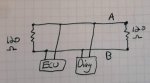
Correct and yes. There is an option to chose, and I have tried all. I believe the transceiver was only used for development of the module, and then was taken out as cost save as not needed. That is how we do ECU's at work, same thing.

I should have studied closely if there was connectivity on the back of the connector, but I did not. I got all excited when I saw all terminals present and I took off with it. Now that I think about it, I vaguely remember there may not be traces up to those pins on the back of the connector. Or maybe there are, and the hardware was not placed on the board, since that is where the cost save would be.
 

aleigh

Well-known member
1,040
49
48
Location
Phoenix, AZ & Seattle, WA
On J1939 links, the resistance across the data pins should be 60 ohms. This is created by a pair of 120 ohm resistors across the pins. Here's the thing - the resistance is not provided entirely (or at all) by the ECU module, it is provided by resistors elsewhere in the application - in the harness, fuse panel, plug blocks, etc. When you designed your adapter, if you did not allow for this, the link will not work, ie, if you just hooked the pins straight up to the diagnostic connector.

Remember old 10baseT with the terminating resistors? 1939 is just like that. You need a terminating resistor on each end of the pair so that you create a bus. The ECU *might* be providing one half, might not. afaik - but not sure - 1708 does not use resistors.

Do you have this covered? Sorry if I am stating the obvious, I just want this to work for both of our sakes and didn't see it mentioned in your other posts.

EDIT - Electrically, it's the same as RS-485. And those USB adapters are ten bucks, not $700. So if we can get something going here I can figure out the msg to read the code and write some software so everyone can have their own code reader. The harness is probably a 60 bucks or less in bits and I doubt it even needs the truck side wiring to just read the code off the ECU. Just a thought.
 
Last edited:

74M35A2

Well-known member
4,145
312
83
Location
Livonia, MI
I just ran a straight harness I crafted up, no built in termination resistors. I hope you are onto something, and it seems so. It tries really hard to connect when I choose one way (takes a long time to finally deny), vs the other protocol, so it seems like it wants to at least. I forgot which was which now. Post a bar napkin drawing of how to connect the terminating resistor(s) and I'll try it this weekend. Not sure if they should be in line with each bus wire, across the two, one each to ground, other.... I have read about it elsewhere also. The wye ("Y") harness I built up does work (is correct, anyway) as my CTIS functionality is 100% when installed, so there are no mis-pins, and I checked it about 4 times from each direction not only when assembling it but also after. Yes, I purchased the NexIQ adapter and installed it's software. I believe this contains "decoding" or translation, as you mentioned, not just a hardware connectivity device. Connectivity from the laptop to that is perfect, plug and play really. Thanks. Exciting to possibly have found a missing piece of the treasure map. It looks like it needs 60 ohm of resistance on each end, and the purpose it to prevent reflections? I would think the CTIS module and then the NexIQ adapter both have these built into them, since they are the terminating devices. I could measure and then know for sure, right? Also, the bus cables I ran are just straight wire, not twisted or shielded. I did not think there would be enough (or any, really) activity from other surrounding wires to cause interference. Especially with the vehicle off, just the ignition and battery switches on. It is easy to say "you need them", but really? In this case, maybe not.... I can see measuring and adding the termination resistors first, and seeing if it works, before twisting and shielding the lines. Let me know if you strongly disagree.
 
Last edited:

74M35A2

Well-known member
4,145
312
83
Location
Livonia, MI
Sorry, my post formatting still is not permitting paragraph spacing. It looks nice and spaced when I type it here in this draft box, and then when I hit "post reply", it all gets jammed together. Ugh.....
 

aleigh

Well-known member
1,040
49
48
Location
Phoenix, AZ & Seattle, WA
The bus needs to be terminated because it uses RF signalling instead of just straight voltage signalling. It's essentially an antenna. The terminators prevent reflections at the end of the wire which would otherwise arise due to the impedance mismatch at the end. There are two advantages to this sort of scheme; longer distances (RS-485 is good out to like a kilometer, something like that) and you can attach multiple nodes. e.g., every ECU can be on the same bus.

I have provided two choices for how to wire it. Either will work. I offer both because maybe one is more convenient for how you have already built the adapter. In the version with the resistors on the ends (instead of the devices) you can attach more than 2 nodes. In the version with the devices on the ends, there can only be 2 nodes.

It's not my opinion that twisting the wires matters in distances you would measure in inches. It's for noise rejection as you have already surmised. If you want to try that though, you can just use some network (cat5) cable, it's close enough. Each pair shares a color, so you can use like blue and blue/white, etc. If this doesn't work untwisted, I might try twisted just because hey you are already there right.

Do you have access to an o-scope?

Hey and no matter what comes out of it thanks for all your effort in this. It's a service to the community.

yes - the NexIQ provides the protocol stacks for the J protocols and then the shim API. That's valuable I suppose and clearly they think so. I don't need that in order to build my own CTIS interface, I can provide my own implementations of the stacks, so all that is required to build a code scanner is the hardware interface. In this case the $10 adapter.
 

Attachments

Last edited:

aleigh

Well-known member
1,040
49
48
Location
Phoenix, AZ & Seattle, WA
Followup - I didn't see your other observation. No, it would not be normal for the ECU or the NexIQ to contain the terminating resistors. The reason being that they don't know how you have the bus wired in the application. What if you are connecting it to a bus with 4 modules on it? If they throw in another resistor that will just break the bus.

The way it "usually" works, AFAIK, is the diagnostic port in the cab (the one that would have been under the dash) is terminated and located at one end of the bus and then the far end of the wiring harness is terminated. The ECUs all hang off the middle. But of course this is no requirement, there are a lot of ways it can be wired. The diagnostic port could be in the middle of the bus at which point the ends are going to be terminated, etc.
 

74M35A2

Well-known member
4,145
312
83
Location
Livonia, MI
Understood and thanks. I will go with A since that best describes the system I have already. If still NG, then I will try a length of the Cat 5 cable, that's a good idea for ready-made, I used to twist wires with a drill. I added to my post later, so that's why it did not appear. You missed nothing. I do have ready access to several good scopes if need be. Let's hope we don't need them. No thanks needed. This is kind of like snowboarding for me (even though I'm old now, 43), I suck at it, but very much enjoy the challenge of attempting to do something I can not naturally do easily. I was going to charge a minimal amount to change target tire pressures on modules for those that wanted to, in an effort to recover at least a small portion of the adapter investment, no profit interest, just to lower my investment cost. I wanted to be able to loan the adapter out, but could not come up with a good way of making sure it didn't walk away, either accidental or deliberately. At the same time I did not want to be asking members to plunk down a $750 deposit, though several readily offered immediately to do so. Not everybody has that kind of cash readily available, I get it, and I wanted it to be available for any and all members. Next best thing would be to bring it to rally's and offer free use of it, but even that is limited in geography. If you could develop a low cost adapter, CTIS systems may go from being removed, to being sought after for adaptation to earlier gen vehicles. If there is a way to pirate the NexIQ software/HWIO/firmware/etc..., let me know what I can do to help, as their adapter is sitting new in box on my workbench. Like buying Turbo Tax software or a movie or music CD, I think it is actually legal to do so once you own it, as long as you are not profiting from doing so...... :) 
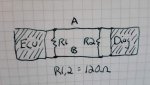
I know the Chinese did it and cloned the earlier versions of the NexIQ, but many that bought them said they did not work. You'll find NexIQ adapter for $800, and for $250, and they look the same.
 
Last edited:

aleigh

Well-known member
1,040
49
48
Location
Phoenix, AZ & Seattle, WA
I can implement the interface without doing anything untoward to the NexIQ. Like I said they are providing one implementation of the protocol, but the protocol is well known, their implementation of it is not essential at all. Where having one comes in handy is that by having one (yours, mine, somebodies) we can monitor the Dana software under operation which will save time in learning the code values for the ECU. It's not even necessary to have Dana's software, it just makes it easier. I think my simple goal would be just to have a basic piece of Windows software that can run w/ a cheap adapter and harness just to dump the codes, since 99% of the time that is all anybody wants to do I am guessing. Although at that point programming and reading out the PSI is not difficult.

If we figure it out one possible outcome is you could always sell the NexIQ and recoup probably most of your investment. I have a related problem which is I want to talk to my Allison. Obviously it's very difficult for guys to get our LMTVs scanned, even at cat dealers. A3 guys are probably in the same boat.

I have one of the cheap RS-485 interfaces coming. I need to order an Amphenol plug like you did and build a little deal and then I'll hook it up to my CTIS and see if I can scan the bus. It's just as well because I need a part off the plug to repair my truck-side wiring anyways. Once this is done I can send the J protocol test messages / etc to the ECU and if it works then at least we know there's a good chance my model of controller works, in which case we can move forward. I'm willing to send it to you too, although you said you had one earmarked from a lmtv.

Are they pin compatible between the LMTV and 5 ton? I've not looked.
 

aleigh

Well-known member
1,040
49
48
Location
Phoenix, AZ & Seattle, WA
Oh I should say - failing all this I'll just build a new CTIS ECU from scratch. With an integrated LCD display it could show the PSI and allow operator control of the pressure (raise/lower manually) as well as end-user programming. Then it can just display actual human readable faults. Probably would end up $150ish in parts, I'd give the controller software away for free (I have no interest in making money here). It's not a difficult exercise with something like an Arduino. If a solution like this is of interest to people, please let me know.
 

74M35A2

Well-known member
4,145
312
83
Location
Livonia, MI
For target pressures, it would work. Real time pressure can only be read during pressure test sequences. The system does not have any air pressure on it before the wheel valves unless checking, filling, or deflating the tires, which is once every 15 minutes when not in run-flat mode. One could utilize an aftermarket tire pressure sensor though to do so if desired. It is a single channel system, so only one target and/or real time pressure could be displayed.

I have not yet compared the pin-out of the M939 series and FMTV. They are on separate pages in the Spicer manual, but maybe with just differences in system architecture external to the module.
 
Last edited:

aleigh

Well-known member
1,040
49
48
Location
Phoenix, AZ & Seattle, WA
What I really meant was I think it would be an improvement to just set a PSI, maybe in increments of 5 or 10, and have the system come to that pressure. From my understanding, should be possible with what is already on the truck. Sometimes I just want a little more or less.
 

therooster2001

Active member
824
43
28
Location
Colorado
It's not a difficult exercise with something like an Arduino. If a solution like this is of interest to people, please let me know.
Yes, and interested in helping with the design, and potential manufacture. The other hobby is electronics and I've fab'ed up some custom boards for other projects. I envision two parts, the harness and a self contained processor / remote display panel that has a dash mount or even just a small display forward facing attached to the original ECU that would read out the codes or have simple code to send new pressures. Once we get the harness to work, sniffing out the codes should be easy, and I thought I already saw the diag codes on here already, but maybe I'm mixing it up with the DANA manual. Did you settle on J1939 or J1708? Assuming you went J1939 because of the terminations. I'll start checking the code libraries. I guess all that is really needed is 4 wires max off the harness right?

Good work guys! I have several ECU's to mess with to help validate.
 

therooster2001

Active member
824
43
28
Location
Colorado
And in reviewing the DANA wiring (62), I do see a buzzer and display, I wonder if those are just waiting to be tapped into.

Edit: no display or buzzer, that's another model.. Just the lamp to mess with..
 
Last edited:
Top
AdBlock Detected

We get it, advertisements are annoying!

Sure, ad-blocking software does a great job at blocking ads, but it also blocks useful features of our website like our supporting vendors. Their ads help keep Steel Soldiers going. Please consider disabling your ad blockers for the site. Thanks!

I've Disabled AdBlock
No Thanks