


kb3bf
Member
- 127
- 1
- 16
- Location
- Howard County Md.
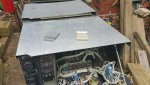
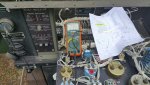
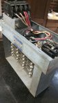
MEP skin work
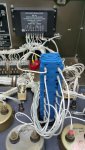
While the weather was not cooperating, i did some sheetmetal work on the missing skins.
It's nice to have a second MEP and have templates for the panels.
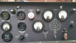
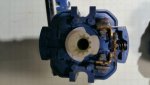
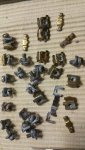
So far I have the top cover and exhaust flap done. I also need a front panel cover (instrument side. For others that's the back side) and the door by the coolant bottle side; but i need to locate a pair of locking mechanisms first.
Any suggestions on paints? I may try stove paint but the color is not going to match for sure.
While the weather was not cooperating, i did some sheetmetal work on the missing skins.
It's nice to have a second MEP and have templates for the panels.
So far I have the top cover and exhaust flap done. I also need a front panel cover (instrument side. For others that's the back side) and the door by the coolant bottle side; but i need to locate a pair of locking mechanisms first.
Any suggestions on paints? I may try stove paint but the color is not going to match for sure.
Attachments
-
 53 KB Views: 25
Last edited:

")