jmenende
Well-known member
- 447
- 364
- 63
- Location
- Puerto Rico
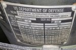
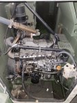
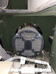
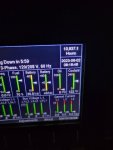
I just got 2 of these units in and its the first time i have seen one. I am impressed with the room available on these to perform repairs or even disassemble. One of the units has 11k hours on it and zero blowby. One thing I noticed was the genhead looks really similar to the 803a but its too bad it wont do 120/240. You can even replace the fuel sender with out having to disassembly half of the unit like on the 1040.
Attachments
-
 100 KB Views: 11
 -
 77.8 KB Views: 11
 -
 55.6 KB Views: 11
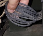
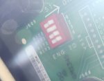
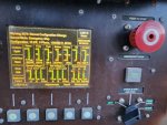
 The available TM's for this set is very inconsistent! So it may not be a 12 wire head even though the -24P shows 12 wires.