• Steel Soldiers now has a few new forums, read more about it at: New Munitions Forums!

  • Microsoft MSN, Live, Hotmail, Outlook email users may not be receiving emails. We are working to resolve this issue. Please add support@steelsoldiers.com to your trusted contacts.


M925A2 snow plow install

Jbulach

Well-known member
Steel Soldiers Supporter
2,590
2,047
113
Location
Sunman Indiana
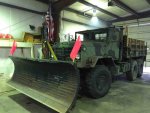
I had to do a bunch of running today, so I didn't get the plow on, but go a little done.IMG_3170.jpgIMG_3172.jpg
Axle links are on within 1 degree of the same angle as the spring, plus same length just 4" forward, should travel without binding.
IMG_3175.jpg
My fat little buddy, trying to help...
IMG_3177.jpg
Got my butt kicked getting the axle out of the inner races of the caster wheel, with bad bearings.
 

Jbulach

Well-known member
Steel Soldiers Supporter
2,590
2,047
113
Location
Sunman Indiana
New bearings showed upIMG_3224.jpgswitching over to a common size (cheap) metric sealed bearing. Now to find somebody with a lathe to shave several thousandths out of the casters bore.
 

Jbulach

Well-known member
Steel Soldiers Supporter
2,590
2,047
113
Location
Sunman Indiana
Well I finally pined the plow on. IMG_3208.jpg
Hopefully I can find another front bumper center section. I thought about making my bumper ends removable, but decided I will build a new center section if I cant find one somewhere.

The plow and table alone weigh 2200 LBIMG_3196.jpg2600 LB at the lift point.

So far birds-nesting doesn't look like it's going to be an issue. I think I'm going to have enough weight in my snatch block and shackles to act as a headache ball, however I may wrap the the last few wraps of cable with duct tape, just to be sure.
 

Jbulach

Well-known member
Steel Soldiers Supporter
2,590
2,047
113
Location
Sunman Indiana
Hey Jbulach, looks good! Post overall truck pics when done! I'm curious as to how the finished install will look as someone who may be getting one of these soon myself.
Well not completely finished, but getting closer.
IMG_3202.jpg661935[/ATTACH]
best I could do, raining outside.
IMG_3200.jpgIMG_3219.jpgIMG_3201.jpgIMG_3214.jpg
 

Attachments

Last edited:

Jbulach

Well-known member
Steel Soldiers Supporter
2,590
2,047
113
Location
Sunman Indiana
So... I spent hours yesterday trying to find the specs for my 24 volt hydraulic pump that I'm wanting to use for my angle cylinders.

The problem is that they offer this model with five different displacement gear sets in the pump, and of course I can't identify mine! They vary from .6 GPM to 2.6 GPM, drawing maximum amperage any where from 70 to 160 AMPs.

Powers not a problem as I'm going to use 1/0 weld lead, and hope to get ahold of one of 74m35a2 upgrades soon. However these GPM numbers have me concerned that it's going to be painfully slow.
Hopefully I can get the correct fittings soon to test it out before I go any further.IMG_3225.jpgIMG_3234.jpgIMG_3230.jpg
 

tobyS

Well-known member
4,820
815
113
Location
IN
First cylinder volume. You have (2) 4" x 20" cylinders. One gallon is 231 square inches. Volume of a circle is 3.14 x 4 (r squared) x the stroke 20". So 12.47 x 20"= 251.3 cubic inches = about 1.1 gal each. Note that you are really just pumping from one side of the cylinder to the other. Since you are working with two, where they are tee'd, it is giving back fluid at the same time, equal to the amount that is being pumped. At first I thought your tank volume was not enough but it should be if you fill the cylinders (both sides) and then fill your tank.

When you turn the plow, the volume of fluid will be the push side (with no rod) plus the rod side (estimate .9 gallon)= 2 gallons. This would be a full turn volume (full left to right or right to left). You can figure the time based on your pump volume from the 2 gallons.

Pump volume of .6 will take over 3 minutes for a full turn and if 2.6, will take about 45-50 seconds.

I hope that pump is double acting. Many that are used on dumps have one side free flow back to tank, which would give you power in one direction, but not the other. I assume the center position is blocked (most dumps are).
 
Last edited:

Jbulach

Well-known member
Steel Soldiers Supporter
2,590
2,047
113
Location
Sunman Indiana
Thanks Toby, that's what I was afraid of.

I may be able to live with 45 seconds, but 3 minutes and I'll have go plan B or C.
$6 worth of fittings is all I'm waiting on to rig it up for a test so I can figure what the flow of my pump really is. I'll also throw an ammeter and pressure gauge on it, as I have a flow chart for pressures of all the different gear options.

Yes, the cylinders a tee'd back to back so theres really no change in tank volume once the system is full.

Fortunately, this is supposed to be a double acting unit.
 
Last edited:

Jbulach

Well-known member
Steel Soldiers Supporter
2,590
2,047
113
Location
Sunman Indiana
Toby,

Tried out that fancy math you taught me! Looks like my lift cylinder is about a third of a gallon.
So... if I can rig my pump to run single acting, I may use it on the lift cylinder as plan B, and angle the plow with the winches hydraulics.
IMG_3249.jpg
Maybe weld a bung in the tank and just dump one hose there?

Wondering about this flow is killing me, might run out and pay $20 for my $6 worth of fittings buying locally!
 
Last edited:

tobyS

Well-known member
4,820
815
113
Location
IN
Uhhhh, if that is the pump you have (in the schematic), start thinking of plan B. It's single acting, gravity return. See the valve portion near C1 with the spring on one end and the square with a dash (that represents the electric coil), that is the valve that lets it down by draining back to tank. It's not a powered function. So your setup will turn your blade one way and until you manually push it back (while holding that valve button), it will stay there. As soon as you start the pump, it will put pressure on C2.

There may be another way to do this but it will require turning the pump on and off. See the first valve. In it's non-energized position, pressure goes to C2 but in the energized position, it goes to C1. So use the normal (non-energized) position to have right turn (only operate the pump, not a valve) and then operate the valve and pump simultaneously to go the opposite direction.

So if speed meets your requirements, it does appear there is a combination that will work (may take modification). But I do think to hold in a center position, you will need a pilot flow control on each line.
 
Last edited:

Jbulach

Well-known member
Steel Soldiers Supporter
2,590
2,047
113
Location
Sunman Indiana
Ok, I guess best possible news.

My hydraulic unit is double acting and takes 52 second to turn fully one direction, which puts me at 2.25 GPM at 350 PSI, and according to my chart 2.6 GPM at 0 PSI.

So I think I can live with this for know if I don't get my lift cylinder mounted this winter.
If I where to use this pump to power my 3x10 lift cylinder, worst case should be 1.125 GPM at 2500 PSI for a raise time of 17.5 seconds.
IMG_3250.jpgIMG_3251.jpgIMG_3252.jpgIMG_3253.jpg
Now to get the pump mounted and the bumper off!
 

tobyS

Well-known member
4,820
815
113
Location
IN
"takes 52 second to turn fully one direction, which puts me at 2.25 GPM at 350 PSI"

Did you hook it up and time it? You say it's double acting...did you make it turn in both directions yet? There appears to be a way but I don't think it's plug and play.


Jbulach

Well-known member
Steel Soldiers Supporter
2,590
2,047
113
Location
Sunman Indiana
Yep. Got my fittings and powered it off the slave port. Cycled back and forth both ways to bleed all the air out of the cylinders. Positively double acting.
 

Jbulach

Well-known member
Steel Soldiers Supporter
2,590
2,047
113
Location
Sunman Indiana
Just had another set back, the previously poorly repaired, bent up, inadequately designed, POS, sheet metal, winch control tower pivot brackets broke loose again. IMG_3245.jpgIMG_3242.jpgIMG_3244.jpg
 
Last edited:

Jbulach

Well-known member
Steel Soldiers Supporter
2,590
2,047
113
Location
Sunman Indiana
Can't read or speak for the schematic. Maybe single acting is the "optional" part?
I had just been going off the characteristics as advertised for label Monarch M-3551. Thanks, I'm glad it worked out for me, as well!
 

big block 88

Member
862
17
18
Location
Topeka/Kansas
Indeed it is. He did not get a picture of the gnome that lives and works in there and assists with winch directional controls but perhaps he was being cleaned up in the parts washer.
 

Jbulach

Well-known member
Steel Soldiers Supporter
2,590
2,047
113
Location
Sunman Indiana
...So, stupid question I know, but is this what's inside where the winch controls are inside the cab?
Two cables hook to the end of the levers and run through the floor. One to the PTO on the transmission, and the other to the winches hydraulic control valve mounted on the inside of the frame rail below the passenger seat.
The brackets inside the tower, that support the lever and and capture the ends of the cable sheath are way to weak and thin and prone to bending an breaking.
 
Top
AdBlock Detected

We get it, advertisements are annoying!

Sure, ad-blocking software does a great job at blocking ads, but it also blocks useful features of our website like our supporting vendors. Their ads help keep Steel Soldiers going. Please consider disabling your ad blockers for the site. Thanks!

I've Disabled AdBlock
No Thanks