• Steel Soldiers now has a few new forums, read more about it at: New Munitions Forums!

  • Microsoft MSN, Live, Hotmail, Outlook email users may not be receiving emails. We are working to resolve this issue. Please add support@steelsoldiers.com to your trusted contacts.


Rebuilding the Injection pump

rustystud

Well-known member
9,071
2,388
113
Location
Woodinville, Washington
I see people where still posting wrong information here after I left.
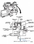
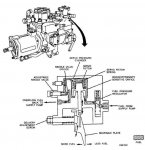
So again I will try and show you how the plate in the FDC still moves all the time.
As you can see from the diagram the wedge plate is connected to the piston which moves according to the pressure exerted against it. This pressure is variable due to the viscosity of the fuel being used and the main fuel line pressure. It's just a matter of how much it moves. The pressure on the regulating valve is not static but will give you a difference value of around 20 PSI . This pressure will change due to the main fuel pressure (anyone with any common sense can see that) but it will maintain this 20 PSI difference due to the spring pressure exerted against it. For anyone who still believes this regulating value just maintains 20 PSI, then explain to me why even have a FDC ? If your pressure is a constant that never changes what is it's purpose then ?
There are two constants in the FDC. The "orifice" in the top of the Servo and the "Servo Spring". In combination with the differentiating regulator valve and the "viscosity" of the fuel used you get movement to the plate which in turns pushes on the governor. There is a "needle valve" after the servo piston but it's purpose is to adjust or "Trim" the servo according to set spec's according to the fuels used. Mainly Diesel and Gasoline and Kerosene . Do not play with this needle valve. You need complicated equipment to set it correctly.
 

Attachments

Last edited:

rustystud

Well-known member
9,071
2,388
113
Location
Woodinville, Washington
I'm rebuilding a spare hydraulic head to swap it and the booster pump onto my engine when I'm confident they are as good as new. There's some kind of sleeve down inside under the 12 point screw that I haven't been able to fish out and clean. It seems to be held in by the oil on the back side. See pic. It turns with no force and a magnet cannot pull it out. Anyone ever removed this? What's behind it?
There is a pressure relief valve under that 12 point screw. You should remove it and clean out the hole.
 

rustystud

Well-known member
9,071
2,388
113
Location
Woodinville, Washington
I got a personal message today about the "droop" adjustment. There has been a lot of confusion about this function so I decided to try and explain what the droop function is for. In one sentence "it maintains engine RPM " .
Now here's an example. In generators when your under load you can have loads drop off immediately. This can cause surging RPM's which can cause serious problems since the Hertz rate is determined by RPM. (In America the 60 Hz cycle is standard. That equates to 900 RPM ,1800 RPM, 3600 RPM's . You get the idea).
So we lost a load on the generator (say someone turned off an A/C unit ) now the generator RPM's is surging (this is bad) , the droop function immediately tries to govern down the engine to prevent this surge. Now lets say the generator is plugging along with a small load. Suddenly there is a air-compressor turned on. Now the engine's RPM's drop fast , the Droop function ramps up the engine's RPM's to compensate for this extra load. That is the function of the "Droop" adjustment in a nutshell.
In vehicle applications you normally don't even need a Droop function. Your foot on the throttle makes this decision. Why the militiary decided to keep this function on there injection pumps I'll never know. Why did they even add the "Fuel Density Compensator" ? Really it serves no useful function. All you guys who bypassed it know this is true. So unless the droop function is extremely out of whack just leave it alone. Playing with it will just add unneeded headaches.
 
Last edited:

Floridianson

Well-known member
Steel Soldiers Supporter
7,390
2,437
113
Location
Interlachen Fl.
Rustystud, I am not ''concerned'' with the droopscrew, I simply asked for clarification.
You made two statements:
That the droopscrew :
1. helps add fuel and 2. prevents excessive fuel delivery
I fully agree with number 2, but do not understand how the droop screw could ever ''help add fuel''.
It is clear that these are two things that are exactly the opposite.That's what my question, still unanswered BTW, was all about.
I am a certified diesel mechanic, so there is no need to explain to me how the governor functions, I learned that decades ago.
I am very familiar with bosch injection pumps, so you will not have to explain the principles of operation.
You can go directly to the droop screw and tell me how it causes what part of the governor to move in which direction in order to add fuel.


I know exactly when and under what conditions the droop screw comes into contact with the stop plate, and when the smoke limit cam does, but neither do I see how having been an apprentice at m.a.n. should make me realize the stop plate is curved, nor how it should be related to the FDC, and I could not find such explanation in the pdf either.
What I did see (and expected) is that the stop plate in the picture has two separate contact surfaces for the smoke cam and droop screw, having slightly different angles.
What I also see is that the pump in the picture is not a multifuel pump, and does not have a FDC. The governor operates on the same principle, however.
The code G pump's (LDS427-2) stop plate is perfectly straight. Smoke limit cam and droop screw are close together, and share the same contact surface.

The stop plates in the other multifuel injector pumps do also have two separate contact surfaces at slightly different angles.
If at all, the stop plate is rounded only where the 2 contact surfaces meet.


According to You, a droop screw ''has no more function'' with the FDC bypassed, as there are no more pressure changes, and the stop plate no longer moves, no longer causing surging.

My explanation, back in post#109, of how the FDC works :
''The pressure inside the FDC only changes when a different fuel is used.
The pressure inside the FDC is the same regardless of engine speed, and does not change during engine operation.''

Differs from yours:
''I think I know what the problem is here. Your not taking into account that the stop plate moves during operation. It is not stationary, but slides up and down according to fuel pressure.''''The stop plate is continually being adjusted according to fuel pressure at that time. Since fuel pressure is adjusted according to engine RPM then that means the FDC is constantly adjusting''

Well, got the tm out, and found this:
''The fuel supply is admitted to a pressure regulating valve where the supply pressure is reduced to a constant regulated pressure over the engine operating speed and load range''

This means the stop plate does not move during engine operation, and even if it did, it would only change maximum load fuel by an negligible amount, between the full load gasoline position, and the full load diesel position.

So your explanations did not answer my question yet.
Oh, and don't get me wrong.
Please keep in mind that my questions are of purely technical nature.
I truly appreciate Your threads. Lots of useful step by step information and heads up even for more experienced mechanics.
I am with you on this one and if you look at the Troubleshooting manual page 33 34 the droop is adjusted after the main fuel and only when we for some silly reason still have the FDC hooked up. It does not add any fuel or decrease any fuel and gen sets do not have an FDC but do have problems with load control so they need one or the other droop controls. When FDC is still hooked up and the wedge plate changes because of type of fuel the Droop should still be with in specs for fuel / boost. Now when we bypass the FDC the FDC wedge plate is no longer moving and all we can do is adjust the main fuel / twin nuts. So if FDC bypassed and you adjusted the main fuel then go to change the droop it will throw off the main adjustment you just set. Just to be clear when we for some reason we still have the FDC hooked up the droop screw if I remember still controls boost fuel from 1600 rpm to 2100 rpm is why it is there.
 
Last edited:

rustystud

Well-known member
9,071
2,388
113
Location
Woodinville, Washington
I am with you on this one and if you look at the Troubleshooting manual page 33 34 the droop is adjusted after the main fuel and only when we for some silly reason still have the FDC hooked up. It does not add any fuel or decrease any fuel and gen sets do not have an FDC but do have problems with load control so they need one or the other droop controls. When FDC is still hooked up and the wedge plate changes because of type of fuel the Droop should still be with in specs for fuel / boost. Now when we bypass the FDC the FDC wedge plate is no longer moving and all we can do is adjust the main fuel / twin nuts. So if FDC bypassed and you adjusted the main fuel then go to change the droop it will throw off the main adjustment you just set. Just to be clear when we for some reason we still have the FDC hooked up the droop screw if I remember still controls boost fuel from 1600 rpm to 2100 rpm is why it is there.
Yeah, basically once the FDC is out of the picture you don't need to worry about the Droop screw again.
 

Floridianson

Well-known member
Steel Soldiers Supporter
7,390
2,437
113
Location
Interlachen Fl.
Greg is correct in saying when at 1200rpm and correct pressure is established the FDC starts to compensate and moves to it correct position for the fuel being used. So it does move from when we start till 1200rpm then settles to the correct position. I have not tested the fuel pressure at 1200rpm so if Rusty says it's 60 psi then that is the pressure where the FDC is doing it's compensation for that fuel. I don't mess with FDC calibration as I will bypass them as soon as I get the truck.
Since digging into the TM's again I was wrong and the FDC with is pressure regulating valve and orifice keep the pressure at 20/ 21 psi. So as soon as the engine starts and we have the 30 psi min. the FDC goes to the setting for that fuel and stays there. Page 1-30 /1-31 TM paragraph C. The 60 psi was for when the FDC is calibrated / tested for leakage on the bench. Guess it pays to read everything even attachments.
Sorry stb64 I have not worked on Deuces for 12 years I switched to the big boys. As a side note if you believe the TM not all IP's had a droop screw like C&D IP's.
 
Last edited:

rustystud

Well-known member
9,071
2,388
113
Location
Woodinville, Washington
Since digging into the TM's again I was wrong and the FDC with is pressure regulating valve and orifice keep the pressure at 20/ 21 psi. So as soon as the engine starts and we have the 30 psi min. the FDC goes to the setting for that fuel and stays there. Page 1-30 /1-31 TM paragraph C. The 60 psi was for when the FDC is calibrated / tested for leakage on the bench. Guess it pays to read everything even attachments.
Sorry stb64 I have not worked on Deuces for 12 years I switched to the big boys. As a side note if you believe the TM not all IP's had a droop screw like C&D IP's.
The FDC plate will constantly move according to what pressure is exerted against the piston. There is no "regulator" in the FDC which would hold pressure at a constant.
During "testing" of the FDC you would use a "constant" pressure and the FDC would be expected to hold the appropriate pressure. That is the only time it would be holding a steady pressure.
 

rustystud

Well-known member
9,071
2,388
113
Location
Woodinville, Washington
OK, since there still seems to be problems with people "visualizing" this FDC movement. I'll post a picture trying to show you what is happening.
When different fuels are used the "Servo Piston" will move into different areas on the "moveable plate" . I've marked these areas to show you what I mean. Now within these areas the moveable plate will continue to move according to fuel pressure.
So for example when using diesel fuel the moveable plate will move up to this area and stay within this area making small adjustments constantly according to fuel pressure.
If you used only Gasoline ( Not recommended !!! ) the moveable plate would move down to this area and stay within this area making small adjustments according to fuel pressure.
Does this make sense for everyone ?
 

Attachments

Redleg130

Active member
51
127
33
Location
Kansas
With a helpful tip from Big Mike, who recommended foot powder on a clean part, I was able to isolate a slow fuel leak to the hydraulic head top center fastener (not sure what to call this) - the one in the center of the fuel lines as they leave the hydraulic head towards the cylinders. Mine has no (rubber) seal on it, just a bevel machined into it towards the bottom of the length of it.

In any case it appeared to have a paint chip on the bevel so I removed that, cleaned the part, and reinstalled it. It runs dry now, so it appears to be fixed. Any tricks to this fastener or is it just holding this part together?

I didn't see this fastener specifically mentioned, or I missed it in the discussion.

I think I found the name, "Plunger bore screw", but no notes or specifics on it.
 
Last edited:

cattlerepairman

Well-known member
Steel Soldiers Supporter
3,173
3,095
113
Location
NORTH (Canada)
You are right about this plug not having any sealing washer. A common jungle fix, when they leak, is to put a copper crush washer underneath. Good that cleaning and re-seating stopped the leak.
As the name suggests, there is a plunger underneath this plug. If your truck won't start and the fuel shutoff is indeed released, one thing to check is that the plunger beneath the plug is moving along its full stroke; if not there is a clip at the bottom that has likely fallen off.
 

Redleg130

Active member
51
127
33
Location
Kansas
Bummer, it didn't hold, it is leaking after driving it a bit, much slower but leaking. I didn't see a torque anywhere, I did 50lbs since I am worried about breaking it. I assume teflon tape or something wouldn't help in this high pressure area?
 

cattlerepairman

Well-known member
Steel Soldiers Supporter
3,173
3,095
113
Location
NORTH (Canada)
The search function is your friend. Torque spec is 65-70 ft-lbs.
See copper washer above.

 
Top
AdBlock Detected

We get it, advertisements are annoying!

Sure, ad-blocking software does a great job at blocking ads, but it also blocks useful features of our website like our supporting vendors. Their ads help keep Steel Soldiers going. Please consider disabling your ad blockers for the site. Thanks!

I've Disabled AdBlock
No Thanks