-
Steel Soldiers now has a few new forums, read more about it at: New Munitions Forums!


M931a1 crane and dump
- Thread starter 8madjack
- Start date

More options
Who Replied?8madjack
Active member
- 416
- 78
- 28
- Location
- Gold country Ca.
Ok, I did a whole bunch of studying up on hydraulic systems and I was reading the tech manuals this morning. There is nothing on rebuilding the single-stage pump but there is a section on rebuilding the 3-stage pump off the m1089 Wrecker. It is basically three stacked gear pumps, and I found references to the single stage pump being listed as a single stage rotary pump. the cross-section is identical to one of the stages on the 3-stage pump so I'm going to assume that it is also a gear pump.
I don't see any reason why the pump that goes to the m939 series truck won't work as long as it meets the specs.
If you want to see for yourself it's in the 34-4 starting at 26 - 2 m1089 3-stage pump repair it comes out to page 434 on the PDF file.
Hoist motor repair starts at 26 - 5 which is page 460 on the PDF.
The following information out of the - 24 on the pump,
Smr code- pafzz
Cage code- 14120
Part# - B5501-33364
I've seen other sections of the site where people refer to the cage code so I'm hoping that maybe I can find some info online using those reference numbers.
One thing missing in the military TMs is an explanation of how stuff works in detail like I would get on say the service manual of my motorcycle. I wish they included that narrative.
8madjack
Active member
- 416
- 78
- 28
- Location
- Gold country Ca.
Also, my apologies to anybody that looked at the TM upload section where I attempted to upload the manuals. I tried several times and for some reason it just wouldn't go through perhaps my connection was too slow I don't have internet at home and I just use my cell phone to tether my computer when I need to. I tried at work with the air card but I just couldn't get it to work. I sent a private message to one of the administrators to just take the thread down since I couldn't add to it
I went to the schematic on the Grove Crane to confirm. The valves all have blocked pressure ports in the centered position.
There are no specs for a 939 series with a pressure compensated system that I have ever seen. I don't know of any gear pumps that can be pressure compensated. They can make the pressure and relieve it to tank.... and in about 15 minutes the oil would be smoking hot. I made that mistake and it cost $7k to replace a JD pump with the right piston Rexroth.
I can tell you don't understand the difference.
I don't have the TM you are referring to. You could bring it up on your computer and then copy the address then paste that here. When you refer to "stages" I think you are referring to piggy back pumps, where one is hooked into the back of the other and the shaft going into the first goes through and powers the second and then even a third. The circuits are seperate. The pump does not feed the flow output of the first, into the second and then that output into the third...in series. I'm not saying some weird method is not employed (as I don't have one to confirm)...government does some strange shi+.
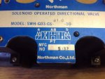
Here is how to tell. Go to your valve bank on the 8 station manifold and take a photo of the top of any of the valves. The legend plate nearly always includes a hydraulic schematic. If the P line goes back to tank in the center position, then a gear pump will work, while if it is blocked and does not return to tank, it is variable flow, pressure compensated. It's not both and one will not work with the other.
I'll see if I have a valve handy to post a picture...how about you get pictures of your valves to compare?
There are no specs for a 939 series with a pressure compensated system that I have ever seen. I don't know of any gear pumps that can be pressure compensated. They can make the pressure and relieve it to tank.... and in about 15 minutes the oil would be smoking hot. I made that mistake and it cost $7k to replace a JD pump with the right piston Rexroth.
I can tell you don't understand the difference.
I don't have the TM you are referring to. You could bring it up on your computer and then copy the address then paste that here. When you refer to "stages" I think you are referring to piggy back pumps, where one is hooked into the back of the other and the shaft going into the first goes through and powers the second and then even a third. The circuits are seperate. The pump does not feed the flow output of the first, into the second and then that output into the third...in series. I'm not saying some weird method is not employed (as I don't have one to confirm)...government does some strange shi+.
Here is how to tell. Go to your valve bank on the 8 station manifold and take a photo of the top of any of the valves. The legend plate nearly always includes a hydraulic schematic. If the P line goes back to tank in the center position, then a gear pump will work, while if it is blocked and does not return to tank, it is variable flow, pressure compensated. It's not both and one will not work with the other.
I'll see if I have a valve handy to post a picture...how about you get pictures of your valves to compare?
8madjack
Active member
- 416
- 78
- 28
- Location
- Gold country Ca.
Here was the best link I found on explaining the details on Hydraulics and according to this you can have a load-sensing gear pump. http://www.hydraulicspneumatics.com...M/Article/False/6401/TechZone-HydraulicPumpsM
Here is the link with the downloadable pdf files. I used my laptop to download everything it's not as mobile-friendly, which is what I'm currently using... phone
I'll have to study the schematics more but there's no mention of it being a pressure compensating system. I'm not trying to be argumentative I'm sure you probably know a lot more about Hydraulics than me but I am a quick study.
8madjack
Active member
- 416
- 78
- 28
- Location
- Gold country Ca.
8madjack
Active member
- 416
- 78
- 28
- Location
- Gold country Ca.
I'll go unwrap the crane right now it looks like there's a break in the weather
8madjack
Active member
- 416
- 78
- 28
- Location
- Gold country Ca.
I hope these pictures are good enough of the routing of the hydraulics to the hoist.


Last edited:
8madjack
Active member
- 416
- 78
- 28
- Location
- Gold country Ca.
I couldn't read any valve diagrams the military painted everything
Okay....going back through I see a little bitty note that says: "Hydraulic system is in by-pass mode when hydraulic system no longeroperates."
So there is a bypass mode (a separate valve) that takes the place of "open center". Your function valves will still show a closed t port, but flow is being relieved. Bypass mode opens pressure to tank. When closed, it builds pressure until it reaches the relief valve setting (milliseconds). On the diagram it says :Main Hydraulic Relief valve and is in about the top middle of the manifold.
That valve would provide a flow path for the pressure to go to tank. This may be the way they use gear pumps....I've done it in sawmill hydraulics when doing it right with PComp was not an option.
When you have a need for a function and pull the lever or use the solenoid, something (electrical) operates the bypass valve at the same time it operates the function valve. It closes and builds pressure, which then is either used for work or relieved back to tank.
Any function, in addition to operating it's own valve, must close the relief valve at the same time. That's a serious level of complexity that isn't necessary with the PC pump. If you have it working correctly, then a gear pump can be used. I had not thought of doing it that way and had not noticed the note before.
I don't know how complete of a unit you are working with...if it has all the interlocks and wiring and relays to control valves simultaneously? If it is entirely complete, it appears you can have a gear pump. While pressure comp would work better, this method was their choice, probably because of the higher pump price. If it works for you, all is good.
And I'll add that when using your dump, it will have to close that relief valve also, or else it will never build pressure, it will take the path of least resistance back to tank, which will be the open relief.
Last edited:
8madjack
Active member
- 416
- 78
- 28
- Location
- Gold country Ca.
It's complete and I saw a video of it operating just prior to its removal from the truck. The gear positive flow system is the most common from everything I have studied and I know my tractor has a positive flow gear pump for the backhoe and loader and it works great
8madjack
Active member
- 416
- 78
- 28
- Location
- Gold country Ca.
From what I've read gear pumps are very reliable inexpensive and very forgiving of contaminants which would make sense for the military to want that
8madjack
Active member
- 416
- 78
- 28
- Location
- Gold country Ca.
Makes sense.
Did those pictures help you understand whatever it is you were trying to figure out with the brake?
Did those pictures help you understand whatever it is you were trying to figure out with the brake?
Very Good! That's much help/I hope these pictures are good enough of the routing of the hydraulics to the hoist.
View attachment 720404
View attachment 720405View attachment 720406View attachment 720406
View attachment 720407View attachment 720408View attachment 720409
Picture 5 and 7 especially helps me to see the hookups. The small line coming from the winch motor valve is the brake releasing line and the line from (what appears to be motor case drain) goes to the outermost port on the brake. This confirms the schematic. I still wish I understood what is happening with the one from the motor to the spring chamber on the brake (that pushes it tighter, not releases). I'm confident I can make the winch I have work now. Thanks
Last edited:
One more thing re your pump. The crane schematics give a flow rate in GPM for every function. The largest I see is 12 GPM. Don't get a pump too much larger than that or the bypass valve will not relieve the pressure. Get a pump around the 12-15 gpm range. Compare to the M929 pump at about 28 gpm would be way too much pump for your setup.
8madjack
Active member
- 416
- 78
- 28
- Location
- Gold country Ca.
Sweet that's awesome! Got done just in time it is dumping out here right now! You'll probably have it working before I have this thing running on my truck, but if for some reason you don't, I'll be able to do more detailed pics once I can unfold the crane.
The use of the dump valve on the manifold makes it work for either type pump. I haven't looked at the wiring diagram, but the operation of any other valve would have to close the dump valve so every valve must have an electrical switch.Sweet that's awesome! Got done just in time it is dumping out here right now! You'll probably have it working before I have this thing running on my truck, but if for some reason you don't, I'll be able to do more detailed pics once I can unfold the crane.
I've made an offer to buy one....the entire crane. I'm thinking of putting it so collapsed down, it sits lengthwise behind the cab, not sideways. (M35A3 4x4) I'll change it to a top winch, from the underside too.
8madjack
Active member
- 416
- 78
- 28
- Location
- Gold country Ca.
It looks like that when I was looking at the crane. Thats cool! I dont know about mounting it inline, but you can probably mount the base normally and nest it inline with the frame. You do plant to keep the outriggers right?
- 108,333members
- 163,629threads
- 2,302,475posts
- 1,153online users