- 7,390
- 2,437
- 113
- Location
- Interlachen Fl.
Good luck with it and I might use Lucas gear oil stabilizer with the heavy weight gear oil to keep temps. down.
Steel Soldiers now has a few new forums, read more about it at: New Munitions Forums!


Not sure exactly.. the fellow with the knowledge doing that end of the work (Chris Jones) knows. I'll ask him and report back...... Roughly what did your driveline angle come out to be?
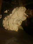
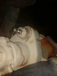
Yes in my conversations with Chris he did say typical down slope desired is a line thru the crankshaft right to axle yoke. As discussed earlier in this thread; when we discovered this was way off on my truck.... we thought something was fubared. Asked about that in thread linked and it was brought up that on these trucks the line thru crankshaft to tranny output is actually an up slope purposefully. Designed that way because the 3 degree down would have put the front driveshaft output way too steep for such a short drive line. So it was done with the down slope instead being toward front to give the front drive line that nice 3 slope. The rear tranny output though now being up sloped means the rear driveshaft has to pitch down further from ideal ..... but it was decided that this was the lesser of the devil than having the front being way to off from ideal. With this higher pinion conversion this devil has been converted to a "nicer guy" because it helps push things much closer to an ideal design. Maybe that is why the military went to all of them being high pinion with later A1's?but I think I remember you want to avoid a “perfectly” straight dive line, and wanted a least 2-3 degrees angle on the u-joints.
As I mentioned in that thread, the Army documentation claims it was done because of lubrication requirements of the engine.Designed that way because the 3 degree down would have put the front driveshaft output way too steep for such a short drive line. So it was done with the down slope instead being toward front to give the front drive line that nice 3 slope.
Also, they originally had double-cardan joints to help deal with the angle, but they were weaker.ADA416765 said:The vehicle is required to operate on a 60% grade. Tilting the engine slightly off horizontal helped the oil lubrication in this condition. This tilt also improved ground clearance for the [24"] step test and off-road performance. This tilt, however, increased the rear driveshaft angle.
The reason to be clear about the cause is that if you don't care about operating on a 60% grade (31°), you could adjust the engine tilt if you wanted to. You could also try to go back to a double-cardan joint, possibly with a larger u-joint, or other design to improve robustness. Or you could try the Rzeppa-style CV, which the study seemed to show was superior in all tests except water intrusion.ADA416765 said:The original design of the FMTV as provided by Steyr at the beginning of the FMTV program used double cardan constant velocity joints in the front positions on all vehicles and on the LMTV rear position. The design experienced durability issues associated with these driveshafts on test vehicles. This prompted the change to single cardan joint driveshafts.
have heard both.... yet do not know if the design of slope done to help front drive line angle was mentioned earlier cause it was documented as well....... or not. Curious if any other CAT applications also slant up instead of down??? IF CAT's with this engine design is are also up slopped.. that would certainly support what you saw in the documentation.As I mentioned in that thread, the Army documentation claims it was done because of lubrication requirements of the engine....
I haven't seen an actual Army document that mentions anything about it having been done to improve the front driveline angle. I generally read everything very carefully, Army documents and forum posts alike, and the only mention of the front driveline angle theory that I've seen has been here on SS in posts. In other words, I've only "heard both" on here, nowhere else yet. That doesn't prove a source doesn't exist, but personally, I'm beginning to find it increasingly unlikely. It would be good to see if other machines/trucks that use the engine tilt it forward too, especially 4WD things.have heard both.... yet do not know if the design of slope done to help front drive line angle was mentioned earlier cause it was documented as well
I would certainly like the ground clearance gains too. I wonder if there were other reasons they switched to it, because it seems like a big/complex/expensive change to make when they could have just used a Rzeppa-joint shaft with a better dust seal to solve the angle issues.Either way the High Pinon seems to be working well for the military since they switched to that design.
you got a way better detail memory than I in your doc. reading. Good quality to have. Thanks for adding your insights from this.I haven't seen an actual Army document that mentions anything about it having been done to improve the front driveline angle. I generally read everything very carefully, Army documents and forum posts alike, and the only mention of the front driveline angle theory that I've seen has been here on SS in posts. In other words, I've only "heard both" on here, nowhere else yet. That doesn't prove a source doesn't exist, but personally, I'm beginning to find it increasingly unlikely. It would be good to see if other machines/trucks that use the engine tilt it forward too, especially 4WD things.
I would certainly like the ground clearance gains too. I wonder if there were other reasons they switched to it, because it seems like a big/complex/expensive change to make when they could have just used a Rzeppa-joint shaft with a better dust seal to solve the angle issues.
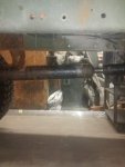
How much did you have to shorten the rear driveshaft with this axle? I wonder if that is a benefit (or possibly a defecit, for some other reason)?
I agree with you and wasnt going to weigh in about it until I read your post. Anyone can spend as much money as they like on their truck and do 'upgrades' in any way they wish, as long as it isn't aimed to influence others and make false scientific claims.I haven't seen an actual Army document that mentions anything about it having been done to improve the front driveline angle. I generally read everything very carefully, Army documents and forum posts alike, and the only mention of the front driveline angle theory that I've seen has been here on SS in posts. In other words, I've only "heard both" on here, nowhere else yet. That doesn't prove a source doesn't exist, but personally, I'm beginning to find it increasingly unlikely. It would be good to see if other machines/trucks that use the engine tilt it forward too, especially 4WD things.
How much did you have to shorten the rear driveshaft with this axle? I wonder if that is a benefit (or possibly a defecit, for some other reason)?
We get it, advertisements are annoying!
Sure, ad-blocking software does a great job at blocking ads, but it also blocks useful features of our website like our supporting vendors. Their ads help keep Steel Soldiers going. Please consider disabling your ad blockers for the site. Thanks!