• Steel Soldiers now has a few new forums, read more about it at: New Munitions Forums!

  • Microsoft MSN, Live, Hotmail, Outlook email users may not be receiving emails. We are working to resolve this issue. Please add support@steelsoldiers.com to your trusted contacts.


MEP803a tripping overload fault while other unit chugs along no problems.

Farmitall

Well-known member
Steel Soldiers Supporter
544
274
63
Location
Eubank, KY
The amount of work you have done, I'm betting your problem is with a mis wired hookup. I had a unit with a similiar problem and I checked everything like you. I double checked the wiring and everything checked out, then I was taking S8 out of another unit to switch them around and noticed it was hooked up alittle different. So I went and compared the 2 units and sure enough, the unit that was tripping overload had 1 wire on S8 hooked up different. Sure enough that was the issue the whole time, the wire was hooked 1 spot off. When I was verifying the wire hookup, I made the mistake of looking to fast at S8 numbers and was just glancing at the wire numbers and the S8 numbers.
Thanks, I read the post a while ago where you explained that. It spurred me to go and recheck all my connections on the defective unit.

I replaced both S6 and S8 in this unit last summer, wiring them per the schematic, and had a working unit right beside it to compare. I will go back over it, checking each wire number, point to point, using an inspection mirror and a good light.

The time spent on this is not a problem, I get to it when I can, weather permitting and have a working unit to rely on.

This has proven to be quite the challenge so far.....but the consolation is becoming familiar with it.

Oh well.....drink water and drive on. Will keep updating as it progresses.

If I happen to find the offending condition, I will photograph it for posterity.��
 

Farmitall

Well-known member
Steel Soldiers Supporter
544
274
63
Location
Eubank, KY
Well, spent a little more time on the 803 today, checking and cleaning connections and checking wire numbers. Breezy and cold but sunny.(good lighting)

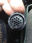
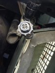
I pulled connections at J5-P5, J6-P6 and J7-P7 apart and found some corrosion in J7-P7.( see pic)
Cleaned them up with cleaner and small bristle brush, let them dry and did point to point continuity checks per schematics....all good. I realize that some of these are not associated with the output end of the set but they needed cleaning so its just another step in the right direction.
image.jpgimage.jpg
 

Guyfang

Moderator
Staff member
Moderator
15,843
22,005
113
Location
Burgkunstadt, Germany
This is a very common problem. I also test point to ground, where possible, as these wire harnesses tend to rub through sometimes.
 

Farmitall

Well-known member
Steel Soldiers Supporter
544
274
63
Location
Eubank, KY
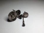
Stopped by my local Harbor Freight store to pick up a few things including zip ties for the harness and found these (stainless) for cleaning up terminals and terminal boards along with electronic parts spray cleaner.
They fit the dremel tool extension ( like a dentists drill)and should make it easier to get into the smaller places.image.jpg
 

Farmitall

Well-known member
Steel Soldiers Supporter
544
274
63
Location
Eubank, KY
image.jpgimage.jpgimage.jpgimage.jpgHad another decent day today so I went back to the generator.

Unbolted the current transformer from the back of the housing and disconnected primary leads from the terminal board and cleaned them, tidied up the primary windings with a couple of zip ties, then pulled the terminal board TB3 out and removed all the screws and cleaned the pads on it. Also cleaned the T1 thru T12 wires from the generator.

Being very careful and using much finesse, I removed the current transformer secondary leads and cleaned them. I know that each core in this transformer is the same, the casing is symetrical but I don't understand why when part numbers, specs and terminal designations are labeled and stamped into one side, someone would mount it upside down.

I took some winding resistance readings talen with Fluke digital meter all leads isolated.

T8--T11 = .3 ohms , T3--T6 = .2 ohms, T7--T10 = .2 ohms , T5--T2 = 0 ohms, T4--T1 = 0 ohms, T9--T12 = .1 ohms

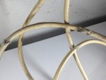
Then proceeded to pull the load terminal board along with the wires going up to K1. When I pulled the wires down from the box, I noticed a brown chaffed spot on the load wires .....was hoping this might be my problem but its not as the insulation is still intact on each of them....with just some fiber braid worn. I will reinsulate the spots on each one and put each in split loom when I reassemble.

I have that assembly inside and am cleaning and rebuilding it, removing all the corrosion and testing the varistors and capacitors for shorts.

I sprayed the bell end cover plate screws with some PB Blaster to let them soak overnight. I want to pull that cover and inspect the windings and end bearing while the way is clear.

Step by step.....gettin' it done.
 
Last edited:

Farmitall

Well-known member
Steel Soldiers Supporter
544
274
63
Location
Eubank, KY
Another nice day today, 50's and calm.

Finished cleaning up TB2 load terminals, waiting on some stainless hardware being delivered tomorrow to use on the varistors to reinstall it.

Reinstalled TB4 and reconnected the generator wires T1- T12, then reconnected all the other wires according to the schematics.

Remounted the current transformer using new stainless hardware and dressed up the wiring harness underneath it with zip ties.

Rechecked (again) all the connections on S8, S6, TB5, S1, TB6, according to the schematics and retorqued all the screws.

In for a bite of lunch then back to it to remove the bell end cover to examine what is visible of the windings and to have a look at the end bearing.

Tomorrow, I am removing the top of K1 and examining the contacts inside it.

Driving on.
 

Guyfang

Moderator
Staff member
Moderator
15,843
22,005
113
Location
Burgkunstadt, Germany
The damage to the wire in the last picture looks more like overheating then chafed wiring.

You wrote about looking into K1 in post 30 and 31. Thought you had done that before. Don't be suprised if you find moisture in it. But don't think that's the problem. I "think" but can't remember, that there might be a thermo circuit in K1 to kick it off in case of overload/ short circuit. Do not quote me on this. Look at it.
 

Farmitall

Well-known member
Steel Soldiers Supporter
544
274
63
Location
Eubank, KY
The damage to the wire in the last picture looks more like overheating then chafed wiring.

You wrote about looking into K1 in post 30 and 31. Thought you had done that before. Don't be suprised if you find moisture in it. But don't think that's the problem. I "think" but can't remember, that there might be a thermo circuit in K1 to kick it off in case of overload/ short circuit. Do not quote me on this. Look at it.
Yes, I had mentioned delving into K1 before but didn't get to it.

This unit has corrosion problems and I am working through them bit by bit. I look upon this as an educational experience more than an exercise in frustration.

I am both mechanically and electrically/electronically trained so none of this is new to me. Working through the pages of schematics as opposed to maybe a 20 or 25 page complete fold out is what is time consuming.

I have worked on all kinds of machinery, all kinds of electrical/electronic circuits, and never had a machine kick my ass......and this generator will not be the first......its too simple.

Come **** or High Water, I will remedy this generator of its issues.:beer:

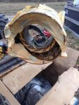
Got the end cover off (broke one screw) and looking at the main stator windings, there is evidence of previous thermal overload on the windings. The threading that is daisy chained, tieing the windings together is melted in two places.

The bearing is rusty as all get out. There is sand and grit on the bottom like it was on a beach with the waves rolling into it.

Looks like I will be pulling this generator head off the engine for replacement or reworking.
 
Last edited:

Guyfang

Moderator
Staff member
Moderator
15,843
22,005
113
Location
Burgkunstadt, Germany
Ok, ok. I was not being critical. You have done great work on this set. Displayed more then casual acquaintance to electrical theory and hands on ability. I just tend to perhaps have read more into what you wrote in massage #30. When a problem runs on this long, I often go back to the start to look at what we may have forgotten. So I was not sniping, just looking for a clue. If I sounded like I was being critical, I wasn't.
 

Farmitall

Well-known member
Steel Soldiers Supporter
544
274
63
Location
Eubank, KY
Ok, ok. I was not being critical. You have done great work on this set. Displayed more then casual acquaintance to electrical theory and hands on ability. I just tend to perhaps have read more into what you wrote in massage #30. When a problem runs on this long, I often go back to the start to look at what we may have forgotten. So I was not sniping, just looking for a clue. If I sounded like I was being critical, I wasn't.
Guyfang, No offense taken at all. I take all input from you as constructive and informative. I hold your opinion and guidance in the highest regard always.

I am using this set as a learning experience. I have thought from pretty early on that there was an issue with the windings. I wanted to eliminate all the peripheral possibilities first.

My removal of the end cover and examination of the windings just about confirms my predictions. There is evidence of thermal overload with some of the thread they used to harness up the windings being melted. There is sand and grit in the bottom of the generator housing like it was on a beach with the tide rolling into it.

If I have to replace the gen head, so be it. In the mean time, I have become intimately familiar with the ins and outs of the MEP803a.
 

Farmitall

Well-known member
Steel Soldiers Supporter
544
274
63
Location
Eubank, KY
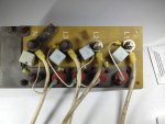
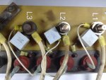
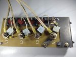
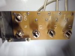
TB2 cleaned up, new stainless hardware and ready for install.image.jpgimage.jpg

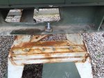
I didn't know that the metal mounting bracket is a copper alloy plate. There was substantial galvanic corrosion between this plate and the case when I removed it.

I will be using stainless bolts and nuts and applying a thin coating of Noalox on the mating surfaces.

Step by step.
 
Last edited:

Farmitall

Well-known member
Steel Soldiers Supporter
544
274
63
Location
Eubank, KY
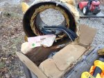
image.jpgimage.jpgimage.jpgimage.jpgA little progress today, unboxed the new stator going into one of my sets and rang out the windings and tested for shorts to ground.....all tested good. A little clean up and some paint and it will be ready to install.

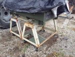
Also, trying to work smarter not harder so I had a couple of roller stands that I scrounged from a local scrap yard last year and decided to bring the work up to a better height and save my back a bit. I used some pieces of steel that these stands had rollers bolted to to secure the generator to the stands so it cannot move.
 
Last edited:
Top
AdBlock Detected

We get it, advertisements are annoying!

Sure, ad-blocking software does a great job at blocking ads, but it also blocks useful features of our website like our supporting vendors. Their ads help keep Steel Soldiers going. Please consider disabling your ad blockers for the site. Thanks!

I've Disabled AdBlock
No Thanks