• Steel Soldiers now has a few new forums, read more about it at: New Munitions Forums!

  • Microsoft MSN, Live, Hotmail, Outlook email users may not be receiving emails. We are working to resolve this issue. Please add support@steelsoldiers.com to your trusted contacts.


MEP-004a or 005a voltage regulator

jamawieb

Well-known member
1,412
512
113
Location
Ripley/TN
So I have a 005a that roasted the T2 transformer in the Static Exciter / Voltage regulator assembly. T2 is the large transformer inside the exciter/regulator assembly. I'm converting the entire VR system to a new self exciting automatic Voltage regulator. The regulator is a ADVR-054 and its a simple install with a 4 wire hook up, I need 2 for sensing (voltage) and 2 for the exciter. But the schematics on the 004a and 005a are junk. I need some help identifying the wires I need, I'm looking for the 2 wire hook up for the exciter. I believe I can use A and B in J9 connector for the connection to the exciter. The confusion is coming from the Bench testing diagram in TM -34 (3-page 284) for the 004a. From the diagram, it looks the voltage comes from the VR to T3 (X1 and X2) then flows out of T3 at H1 and H2 going to the exciter.
Then I need to find 2 sensing wires that actually read the voltage. I believe I can use L and M from J13 for those.
I just wanted validation before proceeding further.
The 004a manual is cleaner to read than the 005a.
 

jamawieb

Well-known member
1,412
512
113
Location
Ripley/TN
Okay, so after some more research you can use pin L and M on the J13 connector for the sensing. Then R and S on J13 are the pins that go to the exciter. I'll report back after I've done some testing to let everyone know of the V/R works.

This will save everyone some time and money. Oshkosh and Delks want $650+ $200 deposit for the entire VR box and exciter. I got the ADVR-054 online for $140 that will replace the original system.
 

ronneyreal

New member
12
0
0
Location
vian ok
i sent voltage reg to flight systems for our 804 b yanmar yesterday brian clogner it blows 3amp fuse f1 circuit i ohmed the circiut to gen 33 ohms. does any one know wix filter numbers for 804a isuzu oil and both fuel and air
 

jamawieb

Well-known member
1,412
512
113
Location
Ripley/TN
Installed the ADVR-054 regulator which is self exciting. Its a 4 wire hookup F+, F-, and 2 sensing leads that I hooked up the reconnection board so it could sense voltage. Started the unit and I get no output. I can put the old (original) VR/exciter back in and hold the start up and the generator will generate power correctly but soon as I let the start switch go, it drops everything to zero. Thus the reason for my conversion attempt.
My question, how does the newer V/R's (like the ADVR-054) know when to excite the field if they have no other connections except the leads to the exciter and the sensing leads to control voltage? The original system uses 24volts to activate the exciter after the speed switch is up to speed so i'm wondering if I'm missing something.
 

kloppk

Well-known member
Steel Soldiers Supporter
1,964
3,056
113
Location
Pepperell, Massachusetts
I'd assume the ADVR-054 requires a minimum AC voltage across it's to sense leads for it to generate any field voltage.
Did you measure what residual AC voltage the new regulator has across it's sense leads?
Could be the residual AC voltage the generator puts out is too low for the new regulator to start working.
Might need to add a field flash circuit to use the new regulator.
 

peapvp

Well-known member
Steel Soldiers Supporter
1,032
1,055
113
Location
Basehor, KS
Jamawieb,

how do you intent to Field Flash your Static Exciter? You got close in your later post that your missing the 24VDC from your start up process

If live would be that simple just hooking up 4 wires, we all would be billionaires........


Okay, so after some more research you can use pin L and M on the J13 connector for the sensing. Then R and S on J13 are the pins that go to the exciter. I'll report back after I've done some testing to let everyone know of the V/R works.

This will save everyone some time and money. Oshkosh and Delks want $650+ $200 deposit for the entire VR box and exciter. I got the ADVR-054 online for $140 that will replace the original system.
 

Scoobyshep

Well-known member
914
989
93
Location
Florida
Yes, I was able to use the advr-054 but I had to buy another one to try. Apparently I toasted the original advr-054 but don't know how. After I installed the new one it worked perfect.
Good to hear, I have a 005 that is getting wonkey. Do you have any notes as to how you installed it?
 

Scoobyshep

Well-known member
914
989
93
Location
Florida
Yes, I was able to use the advr-054 but I had to buy another one to try. Apparently I toasted the original advr-054 but don't know how. After I installed the new one it worked perfect.
I am a bit curious how you got this to work, the manual specifies an output of 15 to 100 ohms. Did you do a full load test?
 

jamawieb

Well-known member
1,412
512
113
Location
Ripley/TN
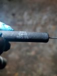
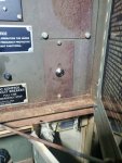
So guys wanted to give everyone an update. The advr054 Works perfect as long as you have residual electricity. I let the unit sit for over a year and started it up, no power. So i installed a simple push button switch to excite the field. I used this push button switch from Oreilly's, then ran power from the Dc circuit breaker right beside my chrome button in the pic below. Then ran a wire from the push button to F1 exciter terminal with the 56ohm resistor and a 5406 diode in place. So if it looses the residual electricity all i have to do is hit the chrome buttonand it generates. Works good. I also did this on another unit for a customer.20211116_211123.jpg20211116_201009.jpg
 

jamawieb

Well-known member
1,412
512
113
Location
Ripley/TN
If using 3 phase 416v or above. I suggest a Marathon se350 VR. I added the same push button excitor to the unit and it does great. That unit is running at 480v 3phase for a irrigation well pump.
 

Guyfang

Moderator
Staff member
Moderator
15,869
22,088
113
Location
Burgkunstadt, Germany
So guys wanted to give everyone an update. The advr054 Works perfect as long as you have residual electricity. I let the unit sit for over a year and started it up, no power. So i installed a simple push button switch to excite the field. I used this push button switch from Oreilly's, then ran power from the Dc circuit breaker right beside my chrome button in the pic below. Then ran a wire from the push button to F1 exciter terminal with the 56ohm resistor and a 5406 diode in place. So if it looses the residual electricity all i have to do is hit the chrome buttonand it generates. Works good. I also did this on another unit for a customer.View attachment 851020View attachment 851019
The OLD,OLD, OLD gen sets all had a switch like this in the control panel. It was "hidden" on the back wall and most folks never looked at it.
 

Jimmie Morgan

Member
62
12
8
Location
Goodman, Missouri USA
I have a MEP 005A 1977 Model. Has been sitting for over 10 years. I have it running good with a Jumper wire to the Engine injector pump. When I turn on the Stop run start switch it does not give any power to the Fuel Pumps or the Injection pump. After I get it running I can push up on the START switch & it will make Electricity. As soon as I let off of it the Current Quits. Anyone have any Ideas without me having to do a BUNCH of checking? Thanks BTW I am 74 years old & cannot fix things like the old days !!!! LOL
 

Guyfang

Moderator
Staff member
Moderator
15,869
22,088
113
Location
Burgkunstadt, Germany
See! Told you someone would jump in here!

Have you ever seen it run right?
Do you have the TM's?
Do you have a multimeter, (MM) and know how to use it?

When I turn on the Stop run start switch it does not give any power to the Fuel Pumps or the Injection pump.

The start run stop switch is S2. Easier to write. By the above statement you mean when you turn the S2 to the Start position? Or do you mean to the Run Position?

I assume, always a bad thing to do, but assume you get the set started by hot wiring the fuel shut off solenoid on top of the IP, (Injector Pump).

Second problem is the set will not make power are you release the S2?

Lets start with one problem first. The set will not Start without the hot wire. I assume you tested the IP Solenoid for voltage with someone else trying to start the set. If not, try that.

With the S2 in the run position, place the S7, (Emergency run switch) in the up position. Do you hear the electric fuel pumps running?
 

Jimmie Morgan

Member
62
12
8
Location
Goodman, Missouri USA
Yes I have it Running But with hot wire to Injector pump. Yes I have the TM's They are driving me CRAZY. Yes I Have Multimeters I was a Electrician in the Navy. When I Flip S2 to the ON Position, The Low OIL light comes on . No power to Injection Pump Or Fuel Pumps. I have the Factory wires to the Injection Pump OFF as not to cause a feedback. When I get it running I held the S2 to the START Position & it makes electricity. Release S2 from start & no Juice. The IP has no power when S2 is in the RUN Position. When I flip the emergency Run BATTLE SHORT switch in the up Position The red light comes on & that is all No Pumps . Both pumps are working when I have power to them. Thanks Buddy !!!
 

Guyfang

Moderator
Staff member
Moderator
15,869
22,088
113
Location
Burgkunstadt, Germany
Yes I have it Running But with hot wire to Injector pump. Yes I have the TM's They are driving me CRAZY. Yes I Have Multimeters I was a Electrician in the Navy. When I Flip S2 to the ON (By on, do you mean start position? Or run position?) Position, The Low OIL light comes on . (It should, there is no oil press when its not running) No power to Injection Pump Or Fuel Pumps. I have the Factory wires to the Injection Pump OFF as not to cause a feedback. When I get it running I held the S2 to the START Position & it makes electricity. (this tells you that the exciter circuit works) Release S2 from start & no Juice. (because that the voltage regulator will not take over.) The IP has no power when S2 is in the RUN Position. When I flip the emergency Run BATTLE SHORT switch in the up Position The red light comes on & that is all No Pumps (This is in the run spoition and engine off?) . Both pumps are working when I have power to them. Thanks Buddy !!!

Its getting late here, so if you can shoot answers back ASAP, I might be able to shoot you some more info.
 

Guyfang

Moderator
Staff member
Moderator
15,869
22,088
113
Location
Burgkunstadt, Germany
OK, Jimmy is going to get back on here and tell us what he found in a few.

That was where I was trying to get you to check, if the S9, Speed switch was tripped. The goo you see is from the Thermal Watt converter in the control cube. Its had a short in it and melted all the potting in it. The reason the voltage drops off when you let the S2 go, is the Volt reg is not working. Its in the A11, Static Exciter. Not good news. There was someone just in the last few days who fixed his VR. I am under from the boss to stop now. Will be back in the morning.
 
Top
AdBlock Detected

We get it, advertisements are annoying!

Sure, ad-blocking software does a great job at blocking ads, but it also blocks useful features of our website like our supporting vendors. Their ads help keep Steel Soldiers going. Please consider disabling your ad blockers for the site. Thanks!

I've Disabled AdBlock
No Thanks