With the card removed the voltage on the blue is gone, just getting power on the pink black like I'm supposed to. As for the LEDs, the green one comes on and stay on when I turn the key, and the red one illuminates when I hit the button for the GPs. The orange one does not come on. According to the instructions, the green means the board is getting power, the red means the relay is for when the relay is closed and the plugs are heating, and the orange is for when the wait light is supposed to be on, so for some reason the card isn't getting power to the light or something, I'm gonna try playing with the card settings and seeing if it changes anything fir the better


 63.9 KB Views: 16
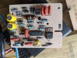 59 KB Views: 18