• Steel Soldiers now has a few new forums, read more about it at: New Munitions Forums!

  • Microsoft MSN, Live, Hotmail, Outlook email users may not be receiving emails. We are working to resolve this issue. Please add support@steelsoldiers.com to your trusted contacts.


MEP-002A Left Connected when Main Power was Restored

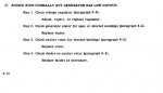
BLUF: After running the genset for hours yesterday in single phase 120/240v mode and powering most of the house, I left my MEP-002A connected to the 240v breaker when I restored Main power to the panel.:oops::oops::oops: Engine runs, no voltage across L0/L1 terminals, i was able to restore voltage to the L0/L3 terminal after switching front panel circuit breaker back to the ON position. Have i fried the genset for 1ph240v and 3 phase generation?

Hello,
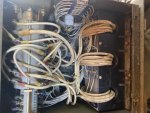
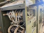
I am a first time poster here, and i joined because this site and forum kept coming up in google when i was reading up on how to get my genset working. I do have TMs for this genset but have not consulted them yet this morning for this issue. As the title suggests, i was using my generator fine during the recent power outage due to Hurricane Michael (10/11/2018 ). I had the selector switch set to Single phase 240V. I set the gen RPM/Hz/Voltage with my Kill-a-Watt meter, ignoring the front panel gauges. Everything worked fine for the duration of the power outage. Around 10 PM last night, when Power Company restored power i turned off the generator and turnoff the breaker to the subpanel where the generator was wired up. I turned on my main breaker and got all my 240v stuff in the hosue connected again. I then realized that my well pump for my orchard, berry patch and livestock was run off the same subpanel where the generator was connected in the Barn. Forgetting that i had NOT turned off the breaker to the generator AT the subpanel, i turned on the breaker FROM the main panel in my house TO the subpanel in the barn. I was doing this while looking out the window toward the barn to verify that the lights came on. When this happened i considered all well and good in the world and went to sleep. This morning i had a niggling feeling in the back of my mind that i had forgotten to turn off that breaker, whereupon i went to the barn to discover the series of event i relayed above. I turned the breaker to the generator off, then went to the generator to see if it would turn over. The generator will start and run, but i initially got no voltage across the plugs. Thinking that i had likely FRIED the generator i hung my head and started poking around on the front panel, discovered the 120V circuit breaker in the OFF position, flipped it to ON and voila! i had restored the 120v across the L0/L3 winding. It appeared to be a double pole breaker, indicating to me that perhaps it would restore both legs of the 240v circuit. However, there is no voltage across the L0/L1 lugs. I cannot locate a breaker for the other leg of L0/L1. Have i fried my generator or is there an internal circuit breaker to prevent idiots like me from toasting the windings? Is it possible i fried one side of the double pole breaker? Thank you in advance for any help you can offer.
 

AceHigh

Well-known member
2,175
29
48
Location
Princeton WV Lake City FL
Welcome aboard. I too have made a few mistakes with one of these gensets but they are tough machines. They almost heal themselves sometimes. Have you tried reflashing the field by turning the switch back to the start position while it is running? There is a protection relay system that should keep the starter from engaging while the engine is running and only flash the field. There is pretty much nothing on these machines that can't be fixed with a little time and patience.

To start with, read through the -12 TM. This is the operators TM, and explains a lot of the things you'll need to know about the operation of the set. If you have not read it, they are TM 5-6115-585-12, TM 5-6115-585-24P and TM 5-6115-585-34. They are the operators manual, the parts manual and the maintenance manual in that order.
 

Guyfang

Moderator
Staff member
Moderator
15,843
22,011
113
Location
Burgkunstadt, Germany
He doesn't need to re-flash the fields. If He has 120 volts at the 120 outlet, then the gen set will make power. Having said that, we aint out the woods yet. First, disconnect the gen set from your barn panel. Isolate the gen set. Start it up. Measure at the input side to CB1, to see if you are getting proper voltage from the main gen to the CB1. You said you turned off CB1, so turn it back on and see if you now have voltage. You may have just damaged the CB1, that's what we need to find out with this test.
 

Light in the Dark

Well-known member
Steel Soldiers Supporter
3,563
5,069
113
Location
MA
So do you not have this wired up with a manual interlock, which would never allow this to occur?
 

Chainbreaker

Well-known member
1,747
1,827
113
Location
Oregon
Also, if you are isolating your generator from house or barn make sure it is grounded once isolated. Once disconnected from your panel's gnd it becomes a "Self Derived System" and needs to be independently grounded via it's own driven ground rod. There is also the requirement to bond/unbond the generator's neutral wire depending on how it is being used (house gnd vs field driven gnd rod).


Edit: Read post #25 and refer to picture in post #29 in this thread (a sticky) if any questions regarding grounding: https://www.steelsoldiers.com/showthread.php?40290-MEP-003A-hook-up-question/page3
 
Last edited:
He doesn't need to re-flash the fields. If He has 120 volts at the 120 outlet, then the gen set will make power. Having said that, we aint out the woods yet. First, disconnect the gen set from your barn panel. Isolate the gen set. Start it up. Measure at the input side to CB1, to see if you are getting proper voltage from the main gen to the CB1. You said you turned off CB1, so turn it back on and see if you now have voltage. You may have just damaged the CB1, that's what we need to find out with this test.
Ok I'll measure at the input of the breaker and see what I get. In looking at the breaker I see that it's a double pole breaker so I would assume that each pole on the breaker corresponds to one of the 120v legs. I'll try to get into the back side of that panel this evening.


Sent from my iPhone using Tapatalk
 

Light in the Dark

Well-known member
Steel Soldiers Supporter
3,563
5,069
113
Location
MA
You really need to look the set over completely before firing it up again. If the set was backfed, you need to make sure the electricity didn't dance around your set and do any damage inside the control box or anywhere else. You got lucky... don't assume luck will look upon you twice. I don't personally find this kind of topic to be a laughing matter.
 
Last edited:

DieselAddict

Well-known member
Steel Soldiers Supporter
2,481
1,878
113
Location
Efland, NC
The exciter circuit takes a beating when you backfeed a set. For sure need to check the rotating diodes and everything else in the exciter circuit before running the set again.
 
Welcome aboard. I too have made a few mistakes with one of these gensets but they are tough machines. They almost heal themselves sometimes. Have you tried reflashing the field by turning the switch back to the start position while it is running? There is a protection relay system that should keep the starter from engaging while the engine is running and only flash the field. There is pretty much nothing on these machines that can't be fixed with a little time and patience.

To start with, read through the -12 TM. This is the operators TM, and explains a lot of the things you'll need to know about the operation of the set. If you have not read it, they are TM 5-6115-585-12, TM 5-6115-585-24P and TM 5-6115-585-34. They are the operators manual, the parts manual and the maintenance manual in that order.
The TOs that I have are the AF manuals listed below:
35C2-3-456-1, 2, 4 & 11

Are these also correct, or do I need to get the ones you mention?

Edit: I see that the AF -1 TO Is the same as the TM5-6115-584-12. You listed the 585-12 though...?

Sent from my iPhone using Tapatalk
 
Last edited:

Guyfang

Moderator
Staff member
Moderator
15,843
22,011
113
Location
Burgkunstadt, Germany
All the TM's here in the TM forum, are the most up to date manuals. If the date and number of changes to each TM are not the same as what in here in the forum, you are using out of date manuals.

The 584-12 is for the 5 KW. The 585-12 is for the 10 KW. The TM's are almost 100% interchangeable.
 
Last edited:

Bmxenbrett

Member
602
29
18
Location
NY
If your going to keep your generator hooked up like it is put a cheap disconnect outside right by the unit. These are also way cheaper and easier to replace than components in your generator.
 

USAMilRet

Member
392
15
18
Location
Tampa, Florida
Yeah, do something before you kill yourself, or wrose, kill someone else accidently.

There should NEVER NEVER NEVER be a uninterruptible connection between the generator and the local utility. The method of interruption is up to you but I would suggest something the physically prevents the two sources of electricity ever providing power to the same circuit at the same time.
 

doghead

4 Star General /Moderator
Staff member
Super Moderator
Steel Soldiers Supporter
26,247
1,168
113
Location
NY
Site rules request a state in your location.
 
Sorry for the delay is responding to this. I am in Georgia. I've not done anything with the genset for 2 years since i posted this but it finally made it back to the top of my fix-it list this weekend. The engine will still start and run fine. I suppose at some point in the fiddling with the unit i turned the phase selector switch to the 12 o clock position. Tonight, with the unit off, i turned the switch to the 3 o clock postion to test the 240 output again. I turned it there and fired up tbe unit and was getting ~60 volts across the lugs (thoroughly disconnected from any loads and isolated from the power grid). I turned the unit off and then attempted to turn the selector switch back to single phase (12 o clock) but it seems to now be stuck. In searching around this appears to be a not uncommon problem. As I plan to use it almost exclusively in this postion, i don't care much about it being stuck. So now that i'm getting only 60V on each phase, what is my next troubleshooting step? According to the AF -2 it is to check the voltage regulator, generator stator, rotor, then diodes, in that order.
 

Attachments

Last edited:

Guyfang

Moderator
Staff member
Moderator
15,843
22,011
113
Location
Burgkunstadt, Germany
Before we start jumping to conclusions, lets start easy. There are 4 terminals on the S6, voltage reconnection switch. L1, L2, L3 and LO. Take the side panel off the AC output box. Find the switch. Locate the terminals. Figure out how you can test between the Lo and the other three terminals WITHOUT shocking yourself. Might even make a dry run, to make sure. Then start the set. Measure between LO and the other three terminals. Still got 60 volts AC? If so, your gen set is not getting initial excitation.

Turn off the set. Locate TB3. Fiind terminals 3&5. connect your meter to them. Start the set up. Do you get DC voltage? How much?
 

cuad4u

Active member
268
88
28
Location
St Matthews, SC
MANY selector switches are stuck in one position. If your switch is stuck in the 120 / 240 single position IMO leave it there. For the past 6-8 years I have restored 002A and 003A generators. Many had stuck switches. As memory serves me, over time I was able to "un-stuck" all of them. It takes patience and careful work. Several took a week or more to get "un-stuck". There are threads on this problem. In one of them I wrote a post of how I was able to "un-stuck" them.
 
Before we start jumping to conclusions, lets start easy. There are 4 terminals on the S6, voltage reconnection switch. L1, L2, L3 and LO. Take the side panel off the AC output box. Find the switch. Locate the terminals. Figure out how you can test between the Lo and the other three terminals WITHOUT shocking yourself. Might even make a dry run, to make sure. Then start the set. Measure between LO and the other three terminals. Still got 60 volts AC? If so, your gen set is not getting initial excitation.

Turn off the set. Locate TB3. Fiind terminals 3&5. connect your meter to them. Start the set up. Do you get DC voltage? How much?
Thank you so much for your reply. I’ve attached pictures of the inside of AC control panel. I have found the TB3 block, but I can’t locate a labeled L0-L3. According to the electrical diagram on top, also pictured, I should be looking for wires X17A4, X18A4, X19A4, and X20A4 for L0, L1, L2, and L3 respectively, but those just go directly to ground or CB1. So, where exactly should I be looking for L0-3 on the switch?

i *think I should be looking for the lugs with wires X14,15,16 and 17A4, is that right?
 

Attachments

Those L0-3 should be the metal lugs you would energize to send power out of the machine.
The L0-3 lugs are easy to find and that’s what I’ve been measuring voltage on up to this point, but I thought @Guyfang was wanting me to check were the terminals on the switch itself? I found the X14,15,16 and 17 terminals on the Selector switch device inside the cabinet. I’m going to check those now.

Edit: I'm guess that by checking those wires/lugs on the S6 terminals, you eliminate the possibility of the circuit breaker being a problem?
 
Last edited:
Top
AdBlock Detected

We get it, advertisements are annoying!

Sure, ad-blocking software does a great job at blocking ads, but it also blocks useful features of our website like our supporting vendors. Their ads help keep Steel Soldiers going. Please consider disabling your ad blockers for the site. Thanks!

I've Disabled AdBlock
No Thanks