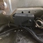
In the first photo, the loom comes in at the top right of image, where one wire (B.) is connected to the top of the glow plug relay and the second (A.) is connected to a ground on the firewall. This must be where the power comes from, as the other set of wires goes forward to the dual fans mounted in front of the radiator.
EDIT: Posted at the same time! How funny. Thank you for the help on the fan controller, I'll be finishing their installation tomorrow.
I believe you are correct on all counts. The power feed for the fan controller is piggybacking off the hot/input lug of the glow plug relay, and the ground wire for the fan controller is terminating at the firewall in the same area. The fan controller is acting as a relay to switch power to the fans, in lieu of a traditional relay.
Beware and Caution: the full current draw of your glow plugs
AND your cooling fans (via the controller) are passing through the red wire present at the annotated (B) lug of the glow plug relay... This wire appears to transit the upper firewall towards the bus bars, and appears to terminate at the lug furthest towards the passenger side of the upper (+) bus bar.
I'd suggest running a separate wire from the (+) bus bar to the power input terminal on the fan controller, and be sure to include an inline circuit protection (fuse, etc) to prevent the fan motors from pulling too much current. Further, I'd suggest upping your feed wire size from the bus bar to the (B) lug of the glow plug relay, as this wire is destined to carry approximately 80 amps of current, based on some other posts I've seen here on the forum... I believe most of the 12v conversions are using a 4-gauge cable, but don't quote me on that.
The second photo is a more macro view, where the batteries connected in parallel instead of series are visible - which is the second piece of evidence suggesting that the truck has been at least mostly converted to 12v. The third photo is a close-up of the rails behind the batteries.
Based on these photos: your front battery is feeding the starter, your rear battery is feeding the upper (+) bus bar, there's a non-original wire feeding your glow plug relay from the (+) bus bar, your rear battery is grounded to the engine block, and it
looks like your glow plug resister bank is still connected to the (+) bus bar (via a blue fusible link), but is NOT connected to the glow plug relay... All appears 12v, as you've noted.
I believe the relay is getting voltage, because the top is energized and the bottom outputs 12v. Would I be able to check each glow plug lead for voltage by putting the voltmeter between the plug and its terminal, to see if the plugs are in fact getting any voltage?
I can't remember if the lead at the top of the relay is running directly to the battery, but I am certain it's getting 12v there. When the relay is closed, it does pass 12v to the bottom lug. Am I right in thinking that this is a glow plug problem?
Based on your comments here, I'd say your glow plug relay is functioning normally and can be excluded.
To verify that you're getting 12v down at each glow plug, simply disconnect any of the connectors from the glow plugs and insert your (+) probe into the connector, and ground the (-) probe (or alligator clip) to a suitable engine ground... No voltage at the GP connector indicates a problem with the harness somewhere between the relay and the plug connector(s).
While you have the connector removed, you could recheck each glow plug's resistance value to ensure that none are shorted or open... You stated that they tested good, so I'm assuming you may have already performed this test on each plug.
Additional diagnostic questions:
1) What type of glow plugs are you using, if known?
2) Is your glow plug controller card installed?
2a) Does your glow plug relay automatically cycle, at all?
3) How long are your holding down the manual glow plug button before attempting to crank the engine?
Additional diagnostic photos:
1) Macro shot of the entire firewall area, from the bus bars to the glow plug relay
Thank you again for your help!
No problem!
![[thumbzup]](https://www.steelsoldiers.com/images/smilies/icon_smile_thumzup.gif "Thumbs Up [thumbzup]")


 63 KB Views: 92


")