


soconnoriv
New member
- 12
- 0
- 0
- Location
- CT
Hello,
Finally got my MA1A unit to spool up and reach no-load governed speed as the manual states. I have one question for anybody that operates them:
Do you have to switch the output air on as soon as you reach idle speed? (100% RPM). Because mine will run for almost a minute and then shut off while idling without any load.
I have not yet turned on the output air because I don't have a hose or anything to cap off the output tube with. Last thing I want to do is over-temp the turbine.
The fuel control unit uses air pressure from the compressor section to control how much fuel is sent to the burner. Without enough air pressure, the fuel control will basically shut off. I have the whole problem pinned to the solenoid valve that allows air to vent from the pressure lines. If I cover the solenoid valve outlet with my fingers, the unit runs no problem, until I stop covering the outlet.
Here's the real problem:
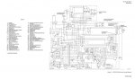
The manual contradicts itself, and states that the 95% RPM centrifugal switch will engage and energize the solenoid valve closed. But if you look at the wiring diagram, there is absolutely nothing that could power the solenoid valve other than the starter relay.
The solenoid valve receives voltage up until the 35% RPM switch de-energizes the starter relay. And when the 95% RPM switch comes on, no voltage is seen. I know the 95% switch works because the ready to load light comes on as expected. The only other thing that will power the solenoid valve is if the output air switch is set to on.
To cut it short, the wiring diagram disagrees with the system description.
Here's a pic of the system description:

And here is a pic of the wiring diagram (Note: On the remote control panel connector, pin C is jumped to B, and E is jumped to F since the remote control panel is not used. Also Item #22 is the 95% switch, while #24 is the 35% switch)

In conclusion, is my unit acting normal? Or should it run without a problem under no load?
Finally got my MA1A unit to spool up and reach no-load governed speed as the manual states. I have one question for anybody that operates them:
Do you have to switch the output air on as soon as you reach idle speed? (100% RPM). Because mine will run for almost a minute and then shut off while idling without any load.
I have not yet turned on the output air because I don't have a hose or anything to cap off the output tube with. Last thing I want to do is over-temp the turbine.
The fuel control unit uses air pressure from the compressor section to control how much fuel is sent to the burner. Without enough air pressure, the fuel control will basically shut off. I have the whole problem pinned to the solenoid valve that allows air to vent from the pressure lines. If I cover the solenoid valve outlet with my fingers, the unit runs no problem, until I stop covering the outlet.
Here's the real problem:
The manual contradicts itself, and states that the 95% RPM centrifugal switch will engage and energize the solenoid valve closed. But if you look at the wiring diagram, there is absolutely nothing that could power the solenoid valve other than the starter relay.
The solenoid valve receives voltage up until the 35% RPM switch de-energizes the starter relay. And when the 95% RPM switch comes on, no voltage is seen. I know the 95% switch works because the ready to load light comes on as expected. The only other thing that will power the solenoid valve is if the output air switch is set to on.
To cut it short, the wiring diagram disagrees with the system description.
Here's a pic of the system description:
And here is a pic of the wiring diagram (Note: On the remote control panel connector, pin C is jumped to B, and E is jumped to F since the remote control panel is not used. Also Item #22 is the 95% switch, while #24 is the 35% switch)
In conclusion, is my unit acting normal? Or should it run without a problem under no load?
Attachments
-
 68.6 KB Views: 9
Last edited: