• Steel Soldiers now has a few new forums, read more about it at: New Munitions Forums!

  • Microsoft MSN, Live, Hotmail, Outlook email users may not be receiving emails. We are working to resolve this issue. Please add support@steelsoldiers.com to your trusted contacts.


MEP-003a No voltage

429
1
18
Location
Berkeley Springs, WV
I will re-test the CVT1 and CT1 at some point. Right now I'm in a crunch to finish the popup camper I'm restoring before I take it camping Friday. I also need to replace the exhaust manifolds on my F150 and the entire exhaust system back from there before then.
 

Guyfang

Moderator
Staff member
Moderator
15,815
21,957
113
Location
Burgkunstadt, Germany
I have once again slogged through this whole thread. Like Ray, I agree that it cant be diodes. It puts out voltage with terminal #17 disconnected on the A1. You have replaced/tested all components in the control cube, (CC). So its got to be in the AC output box. OTHER then a wire that goes from the CC to the output box. Like for instance, the wires to the Transformers, T2 and T3. But that's the only thing I might even think of, and its a way long shot. Simple to test.

But it still feels like its got to be in the output box. You need to pull it off the set, take it apart, and test everything in that circuit.
 

bchauvette

New member
810
12
0
Location
Easley SC USA, 29640
Starter interrupter switch is now working properly. When engine speed comes up, the push rod moves the interrupter switch so the starter doesn't engage while holding the start switch. No voltage at the output lugs, no voltage or frequency on the gauges, no voltage at the convenience outlet.


Is my next test to follow procedure 8-2 in the -34 manual? "Disconnect the voltage regulator at the exciter wires (wires P67C16 at TB3-5 and P60E16 at TB3-6). Connect a 12 volt battery in place of the regulator with the (+) terminal to TB3-6 and (-) terminal to TB3-5. Run the engine with the battery in place of the voltage regulator. If there is output now, the voltage regulator is bad. If there is no output, the main alternator is bad."
FYI


tb3 is under the regulator rectifier you have to remove the blower housing (if I'm wrong please let me know).good luck with the correct wire to un- hook or the locatio on the tb my gen set is not marked. I have no Idea which wire to un hook.
 
429
1
18
Location
Berkeley Springs, WV
OK, back to this, finally. I took the AC output box off of the unit. I've gone back through this thread and I'm about to go outside and test everything you guys have asked me to test so far in this thread. CVT1, CT1, Linear Reactor, A4, T1, T2, etc. etc. etc. Anything I've been asked to check so far in this thread, I'm checking again today. I see no reason to do the battery test again, though. I'll let you know the readings I come up with.
 
429
1
18
Location
Berkeley Springs, WV
With the AC Output Box on my work bench, I took readings. I didn't do anything in the AC Control Box today, but here are the results from the AC Output Box:

Linear Reactor (NEW)
Specification is 13.5 ohms +/- 1.35 ohms
Terminals 1/2 - 13.8 ohms GOOD
Terminals 3/4 - 13.8 ohms GOOD
Terminals 5/6 - 13.8 ohms GOOD


CVT1
Specification is 2.27 ohms +/- .227 ohms on the primary windings
Terminals H1/H2 - 2.5 ohms, then .67M ohms, then open! BAD
Terminals H3/H4 - 2.4 ohms GOOD
Terminals H5/H6 - 2.4 ohms GOOD

Specification is 1.68 ohms +/- .168 ohms on the secondary windings
Terminals X1/X2 - 1.9 ohms BAD (technically)
Terminals X1/X3 - 1.9 ohms BAD (technically)
Terminals X2/X3 - 1.9 ohms BAD (technically)

Specification is 9.6 ohms +/- .96 ohms on the control windings
Terminals C1/C2 - 10.3 ohms GOOD


CT1
Specification is 0.5 ohms +/- 0.05 ohms
Terminals 1A/2A - 0.5 ohms GOOD
Terminals 1B/2B - 0.5 ohms GOOD
Terminals 1C/2C - 0.5 ohms GOOD


A4 Board
Specification is low resistance one way, high resistance the other way
CR1 GOOD
CR2 GOOD
CR3 GOOD
CR4 GOOD
CR5 GOOD
CR6 GOOD

Specification is 56 ohms for R1
R1 is 55.2 ohms GOOD


So, it sure looks like my CVT1 is bad. The initial reading on terminals H1/H2 was probably quick and in specification, so I moved on. The fact that it climbed and then read open leads me to believe that CVT1 is bad. I went back after several minutes and read H1/H2 again and had over 2M Ohms. I'm not fully convinced the secondary windings are actually bad considering they all read identically and they are .052 ohms out of specification, but it doesn't matter if the primary windings are bad.
 
Last edited:

Triple Jim

Well-known member
1,373
277
83
Location
North Carolina
Specification is 1.68 ohms +/- .168 ohms on the secondary windings
Terminals X1/X2 - 1.9 ohms BAD (technically)
Terminals X1/X3 - 1.9 ohms BAD (technically)
Terminals X2/X3 - 1.9 ohms BAD (technically)
It's academic at this point, but did you subtract the reading of the meter leads from the reading you got on the windings? That is, short the probes together, wait a few seconds, and get that reading, then subtract that from winding readings.
 

Triple Jim

Well-known member
1,373
277
83
Location
North Carolina
Well, there is that big problem of the intermittent open on CVT1's H1-H2 winding.

Measuring 1/2 an ohm that way in CT1's windings is difficult. You'd be better off putting an amp though the winding and seeing if you have 0.5 volts drop across it. Or adjust a current though it to get a 1 volt drop and see if it's 2 amps, etc..
 
Last edited:
429
1
18
Location
Berkeley Springs, WV
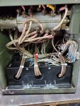
Ray70 sold me his CVT1 and CT1 (I asked for both together) as well as his magnets off of the blower wheel. They came in over the weekend and I put the CVT1 and CT1 in the AC output box today. What a pain that was. I was able to slip some heat shrink onto the chewed wire going around the CVT1 and CT1 instead of using electrical tape that would eventually lose it's stickiness and start unwrapping. I was also able to clean the rest of the mouse crap out of the bottom of the AC output box so it wouldn't smell horrid any longer. I think I got everything buttoned back up nicely and neatly so I shouldn't have any issues. I also cut a thin piece of plexiglass out and closed up the gap between the top of the output lug panel and the back of the AC output box. I'm pretty sure that is how the mice got in so now they won't have a way in.

i-jmMZMNp-XL.jpg


I've only started it once so far. It produces 235v AC between the lugs and 117v AC at the convenience outlet. The Fluke shows 60.02 Hz at the convenience outlet. I'll put some loads on it later to see how it does.


Now I need to go back out and take the blower off again so I can put the new magnets on. Hopefully, that will fix my charging system too.
 
429
1
18
Location
Berkeley Springs, WV
I've run it about a dozen times now. I adjusted the voltage knob so I get 120/240v AC perfectly and it is staying at 60 Hz perfectly as well. Every time it works now. I'll hesitantly call this success, although there isn't much left to replace so I'm fairly confident in the repair this time. I'm going to run it with Triple Jim's VR inside and keep the original board in a box just in case.


I also swapped out the magnets. For the first time ever, I'm getting over 24v at the batteries. It's closer to 25v, but that's better than battery voltage which means it is finally charging a little. I'm going to leave it alone now.


Happy day!
Thank you to everyone who helped me troubleshoot this problem and a HUGE thank you to Ray70 for selling me parts at very reasonable prices.
 

Guyfang

Moderator
Staff member
Moderator
15,815
21,957
113
Location
Burgkunstadt, Germany
Our standard was 6 hours at full load. A little much for civilians, but in the Army, not. I always figured if it make 6 hours, its probably good enough to give out to someone going down range.
 
429
1
18
Location
Berkeley Springs, WV
I don't actually have a way to run it for any length at full load. If I hook it up to my house and run my house, it won't even reach capacity unless my dryer, well pump, and AC unit were all running at the same time for an extended length of time. The house will exercise it plenty well enough anyways, I'd think.
 

Chainbreaker

Well-known member
1,746
1,825
113
Location
Oregon
Running a load of laundry in dryer and running AC unit should allow a good enough 240V balanced load for reliability testing purposes.

BTW, good job sticking with it! You certainly know your generator much better than when you started. You yourself are now officially tested and approved!
 
Last edited:

Guyfang

Moderator
Staff member
Moderator
15,815
21,957
113
Location
Burgkunstadt, Germany
Go to the dump, or scrap yard. Loot some heating elements out of some dryers and make one. There are several threads here in the forum about that.
 
Top
AdBlock Detected

We get it, advertisements are annoying!

Sure, ad-blocking software does a great job at blocking ads, but it also blocks useful features of our website like our supporting vendors. Their ads help keep Steel Soldiers going. Please consider disabling your ad blockers for the site. Thanks!

I've Disabled AdBlock
No Thanks