synelecpb
New member
- 15
- 7
- 3
- Location
- point pleasant NJ
Hi All,
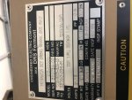
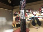
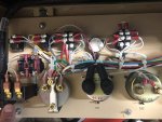
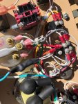
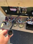
I've been lurking around this community and finally have purchased my own 2011 MEP 831a! I'm having an issue though that I feel like i've seen others have, but can't seem to find anywhere in the threads. Everything works as it should except the fault test button won't light the lights, and there is a plug wired into the control box. I feel like these issues are somehow related, like perhaps this unit was meant to be a slaved unit? Or remotely operated? Any assistance would be most appreciated.
Thanks!
Attachments
-
 65.8 KB Views: 56