• Steel Soldiers now has a few new forums, read more about it at: New Munitions Forums!

  • Microsoft MSN, Live, Hotmail, Outlook email users may not be receiving emails. We are working to resolve this issue. Please add support@steelsoldiers.com to your trusted contacts.


MEP-803A mixed load test results

WillsC

Member
31
0
6
Location
Inverness, FL
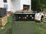
I finished the load bank today which is 4 220V 2500W hot water tank elements and 2 120V 1500W elements in a 55 gallon drum. After a warm up I applied different loads and the Gen handled them fine up to 13k. I let it run about 15 minutes on 10k watts and other than quite a bit of smoke, least more smoke than I thought there would be it did fine. It was all the time I had free so will run it longer tomorrow. I think possibly some of the smoke may be coming from the 10' length of iron pipe as it is new and probably has some oil on it.

There is one issue though. With 2x 2500W so 5k on the gen the load meter just barely moves off 0 at 4X 2500W so 10K the load meter shows about 30%-35% so there is something wrong somewhere. Any ideas?
 

WillsC

Member
31
0
6
Location
Inverness, FL
Zed,

I tried that, don't think this is a calibration issue with the meter. There is not near enough adjustment to get it close to accurate. With the adjustment I can get it to go from 30% on meter to 50% on the meter but no higher at 10kw load. I removed the leads to the ammeter and cleaned them up and made no difference. Clamp on meter shows it is producing 40.9 on one leg and 41.1 on the other.
 

DieselAddict

Well-known member
Steel Soldiers Supporter
2,481
1,878
113
Location
Efland, NC
The load meters are notoriously inaccurate. I personally recommend using your clamp on meter and correlating it to the meter best you can. The next best thing to do is replace the load meter with a more accurate setup.
 

Zed254

Well-known member
866
464
63
Location
S. Hampton Roads, VA
I've been lucky with my 2 load meters and have been able to calibrate them using a clamp on meter. I do have one volt meter that does not calibrate accurately. As Diesel points out they are not very accurate to begin with. Sounds like you will need to replace what you've got....search SS for some options and ebay if you want an original type replacement.

If you decide to go with OEM you want a 60Hz gauge. The only thing I saw on ebay were for 400Hz machines.
 
Last edited:

WillsC

Member
31
0
6
Location
Inverness, FL
That is unfortunate, had hoped there was something I was missing. I can live with a bit inaccurate but off by 50%?? That is just going to bug me. I will see what I can find online as a replacement. Stock or not I don't care about.
 

Daybreak

2 Star Admiral
Steel Soldiers Supporter
1,521
740
113
Location
Va
Howdy,

With the unit off

turn all the switches. They are wiper switches. They need to be turned back and forth to clean the contacts. If it is still a problem, some chemical help might be needed. Electrical contact cleaner and rotating the switches some more.
 

WillsC

Member
31
0
6
Location
Inverness, FL
Hello Daybreak,

In searching a bit ago I did see that. So exercise the switch behind the control panel correct? Tried that turning to all 3 positions a dozen times or so with no luck. I know I am probably not going to like your answer but....for that switch it would require taking the cabinet top off to get the spray to it?
 

robertsears1

Active member
255
118
43
Location
Near Apex/NC
I believe he meant to exercise the switches that you can turn from the outside of the panel. I only have 804s in that series but on mine, there is a rotary switch to the right of the main start switch. You will need to flip the control panel down (at least on an 804) to gain access to the back of the switch. On mine, the whole black area drops down. Should be two twist latches up at the top to let the control panel flip down. Don’t force it but do it around 50 times. You can spray WD40 or tuner cleaner, but the best stuff is called deoxIT.
Robert
 

Attachments

Last edited:

WillsC

Member
31
0
6
Location
Inverness, FL
I think I am confusing everyone including myself.....so when in doubt, pictures:)

This switch?
20190927_154107_resized_2.jpg

Or this switch?

20190927_154052_resized_2.jpg

If it is that second one where exactly in that TOWER that it is connected to the back of the switch do you spray exactly?
 

Zed254

Well-known member
866
464
63
Location
S. Hampton Roads, VA
It's good to exercise S1, S6, S8. S1 and S6 are easy to get to with contact cleaner. S8 not so much. You are just trying to remove any corrosion that has accumulated during storage so you get good electrical contact through the switch. You have pictured S8 and S6.
 

csheath

Active member
713
196
43
Location
FL
You should verify output with a clamp meter and voltmeter that are fairly accurate.

My 803 had a non working hz meter and the power meter wouldn't go over 80% with 13000 watts load. I ordered a digital combo generator meter that read volts,hertz, and hours to replace the power meter. I stuck a couple of volt/amp meters in place of the hz meter and wired them so I could monitor L1 and L3 separate. Eliminates the guesswork.
 

WillsC

Member
31
0
6
Location
Inverness, FL
I have a clamp meter and did verify the output, that post is on the first page of this thread somewhere. It was 39.? and 40.? per leg so the output was there the meter just did not agree. At the 39 and 40 amp output per leg the meter was at like 25-30% and should have read close to 100%. That was 4 X 220V 2500 watt hot water tank heaters each on its own circuit.
 

Zed254

Well-known member
866
464
63
Location
S. Hampton Roads, VA
Zed,

I guess what I'm asking is where to spray the contact cleaner.....just anywhere on the switch and it will get inside???
Drop the control panel down to get access to S1 and S6: I sprayed contact cleaner in the various holes in the body of the switches. The Blue switches have a lot of openings in the body and I sprayed a wee bit of contact cleaner in each and simply turned the switch 25 or so times. You are grinding off any corrosion to make sure you have good electrical contacts. I would also unscrew the wires on your faulty gauges and confirm good tight crimps, no corrosion, tight....but not overly tight....connections. If gauge still doesn't work you should trace the wires to the next contact and confirm no corrosion there. Check ground wires on gauges, too.

For S8 I just exercised it 25 or so times. I was lucky enough not to need to unscrew the panels to get access to that switch: it works well on both of my machines.
 

WillsC

Member
31
0
6
Location
Inverness, FL
I sprayed gunk electronics cleaner in the switches, is all I had on hand but did order some Deoxit so will try that Monday when it arrives. I spun the AM VM switch at least 50 times each direction but made no difference

I did notice something odd that MAY help someone diagnosis the issue.....If I apply the 120V 1500W elements one at a time the meter does seem to respond normally and with two of them on so 3000W total the meter is at 25%. Yet if I flip on one of the 220V 2500W breakers the needle on the gauge does not go higher. So the 2 120V 1500W elements (3000W) register 25% on the load meter but adding 4 X 220V 2500W so 10kW elements only makes it go from 25% to 35%. If I turn on one of the 220V elements the load meter does not even budge off zero yet if I then kick on one of the 120V elements the meter shows that load accurately but ignores the 220V load. If I clamp the output legs it shows the output correctly. So the meter sees the 120V adds but does not seem to see the 220V elements......very confused.

The seller will send me out a new gauge or switch.....like I said he stands behind his products but why ask for a part if I don't know what the issue is.
 

WillsC

Member
31
0
6
Location
Inverness, FL
And on the S1 switch after I sprayed it I noticed it was quite a LOT harder to turn. The switch would actually get stuck at preheat. After turning it a few times to every position except start when I did try to start it all I got was a relay click no start. After a few tries it did turn the engine over and switch seems to work normally now but it had no effect on the load meter.
 

Zed254

Well-known member
866
464
63
Location
S. Hampton Roads, VA
I had a blue S1 switch that would hang on the start position. I replaced it with an Electroswitch 75902LV: this is Rev 3 of the S1 and is a better quality switch.

Your AM-VM switch indicates amps between specific terminals. I use a 240 volt stove for my load bank and it provide a balanced load: meaning the % load meter is indicating a load between terminals that closely match the other 120volt leg when measuring between L3 and N. The L1-L3 is the load between both hot 120volt legs of the balanced 240 volt system.

Is it possible that your load bank does not provide a balanced load? I'm thinking you may have more of your 120 volt heater elements on one leg than on the other 120 volt leg. To test this you could eliminate all 120 volt heater elements and only run your 240 volt elements and see how the % load meter performs.
 

WillsC

Member
31
0
6
Location
Inverness, FL
Zed,

My load bank control is a normal breaker box. a column of 3 breakers for each hot. Each side is 2 220 double pole breakers and one single pole 120 breaker. I will keep messing with it. At the moment running the wire down from the roof after installing the solar panel I took off the top of the gen.
 

WillsC

Member
31
0
6
Location
Inverness, FL
I also checked the wires going to the elements. Each of the wires all 8 of them are carrying just over 10 amps each so elements are all working. It has to be in the wiring somewhere or the switch or meter itself.
 
Top
AdBlock Detected

We get it, advertisements are annoying!

Sure, ad-blocking software does a great job at blocking ads, but it also blocks useful features of our website like our supporting vendors. Their ads help keep Steel Soldiers going. Please consider disabling your ad blockers for the site. Thanks!

I've Disabled AdBlock
No Thanks