• Steel Soldiers now has a few new forums, read more about it at: New Munitions Forums!

  • Microsoft MSN, Live, Hotmail, Outlook email users may not be receiving emails. We are working to resolve this issue. Please add support@steelsoldiers.com to your trusted contacts.


Dump Conversion

Stretch44875

Super Jr. Moderator
Super Moderator
Steel Soldiers Supporter
2,958
28
48
Location
Tiro, Ohio
I changed the title of this thread, since I am posting all my pics and info on my dump conversion. First couple of posts deal with angle of bed, and then install.

What angle of lift would you recommend for a dump bed? I have the hinge installed, trying to figure out where to put the lift.
Thanks,
Dennis
 
Last edited:

mangus580

New member
6,010
282
0
Location
Western NY
Certainly over a 45..... but I would shoot for maybe 60?

If you can wait a couple days, i can probably measure mine for you..... but I wish mine went farther :)
 

Junkyard Wars Crusher

12B20
Steel Soldiers Supporter
That is a great chart. Just about any material you can think of is in there.

A couple of other things to ponder:

1. You may want to consider adding an additional 10,20,30??? degrees for grade - if the truck is not on level ground when dumping, the angle required may be more or less than that stated. For example, if you are backing UP a hill to dump and the hill is 10 degrees slope, then you will need to add 10 to any of the values shown in the chart. Likewise, if you are backing DOWN a hill, the angle required will be less.

2. As indicated in the chart, most wet materials generally tend to stick (surface tension) and have lower tendency to slide. In this case, you may again need a steeper angle.

Jeff
 

mangus580

New member
6,010
282
0
Location
Western NY
Thanks JWC.... I was thinking the same thing. I have had many times where mine wont dump what is in there, and I am pretty sure it hits 45... Backing up into a sileage bunker for instance.... I have had the truck backed up probably a 30 degree or more slope of sileage.... trying to dump. I think alot of farm trucks go to even 75 or so!!
 

JohnnyReb

Member
513
13
18
Location
North Georgia Mtns.
Also want to think about the pressure of the lift created by the hinge point and lift point. Unless you change the bed or double rail bed and/or deuce, you are stressing a bed not made to perform as a dump. The farther back the lift and greater angle, the more psi on the hinge point and lift point. Nothing will turnover a dumptruck quicker than to lose a hinge point or have the bed give while extended (I speak from the voice of experience, so I am extra cautious about these matters).
JMHO
JR
 

JohnnyReb

Member
513
13
18
Location
North Georgia Mtns.
BTY, what type of lift? I have a hydraulic driven by an electric pump and am very pleased with the performance. Especially prefer the power-down as opposed to bleed down. It is slower but allows more control.
 

Stretch44875

Super Jr. Moderator
Super Moderator
Steel Soldiers Supporter
2,958
28
48
Location
Tiro, Ohio
Well I am measuring the lift, and looks like I have somewhere between 7 and 8 feet of lift. The hinge is 1 foot in, so I will be lifting 11 feet of bed. I will have a more accurate measurement when I go to install the lift. That should be plenty, I will be able to put the lift towards the front. Of the people I have talked to, they recommend at least 60 degrees. Didn't think about dumping on a hill, good point. The hinge should be plenty strong, it is off the same truck as the lift, and installed on the deuce. The lift is a sissors style off a grain truck, going to be pto powered.
 
Last edited:

yeager1

Member
335
0
16
Location
Colorado
Unless you change the bed or double rail bed and/or deuce, you are stressing a bed not made to perform as a dump

The last time I put a lift under a non dump style bed, I braced it with 1/2" thick 4x8" angle iron and it made the bed very rigid. Even a 3' or 4' section of some similar material would belp a lot.
 

Stretch44875

Super Jr. Moderator
Super Moderator
Steel Soldiers Supporter
2,958
28
48
Location
Tiro, Ohio
Okay, got some pics up :D

Had fun getting the bed up. Attached a chain to the front of the bed, and to a tree behind the deuce, about 12 feet up. Drove the deuce foward, and up went the bed!

I figured out what capacity lift I have. 6" dia, 29" stroke cyl. Lift has 8.5 feet of stroke. 6" cly has area of 28.2 in^. At 2000 psi that is 56548 pounds of force. 29" stoke to 8.5 feet is a 3.5 ratio, so force at lifting point is 16,156 pounds, or 8 tons. At 3000psi 12 tons. Then I only have to lift approx. 1/2 the load, so plenty of capacity. I knew that math had some purpose in life :D And feel free to double check me, I am not sure if this is correct.

I am bolting the hinge to the bed instead of welding. I plan to add a dropside at sometime in the future, easier to change beds. Used 4 grade 8, 1/2 bolts per side.

The hubs that are for the shaft, of the hinge, are welded into holes in the frame on the outside and welded on the inside.

I am going to weld the hinges to the bar that goes through the frame, at the moment they are free to turn on the shaft. The shaft turns in the hubs I welded in. By welding I will eliminate the chance one hinge will turn without the other one, possibly tilting the bed to the side.

I don't think I will double the frame. Where the lift is going is right on top of a crossmember, that will stiffen it up some. The truck it came out of was doubled, but the deuce frame is thicker and wider than the truck's frame.

The bed is at 55 degress in the pic. Looks like I will get 60 to 65 degrees when I am done. The attachment points for the lift will be about 20in in from the front.

Dennis
 

Attachments

Last edited:

Stretch44875

Super Jr. Moderator
Super Moderator
Steel Soldiers Supporter
2,958
28
48
Location
Tiro, Ohio
Well after many hours of work this weekend, I got the lift installed. The upper part of the lift is just tack welded for now, waiting for a friend to arc weld it. Figured I would let someone who knows what they are doing for the heavy welding, I haven't welding with an arc welder since high school.

The bottom of the lift is bolted to the frame with 3/4", grade 8 bolts.

Ended up with 60 degrees of lift. Lift is mounted in about the only good spot for stability and clearence.

The biggest time was spent on narrowing the lift. It was 1.5 inches too wide, had to cut the ends off, slide the tubes out, shorten them, put the tubes back in, and weld the ends back on. Not much fun when one tube is a 3", 1/4" wall pipe, and the other was 3/8" wall pipe.

Had to do some mild clearence work on the bed, will go back and reinforce where I cut. Also plan to box the bed frame, it is pretty thin channel.

So far I have made 10 1/2" holes, 4 3/4" holes, and 2 holes that where 2 3/4" dia. Had to buy a bigger drill! If you use enough lube, you can use a bimetal hole saw to cut through the frame. Takes a while! Next time I might cheat and get the torch out...

Looks like it will be a while before I can get back to it. Still need to mount the pump, pto, hydrualic lines, and put the lights back on.

Sorry about the quality of the pics, it was dark and raining out by the time I was done... Will get some pics of it all the way up whenever I am able to get back on it.
 

Attachments

Last edited:

Stretch44875

Super Jr. Moderator
Super Moderator
Steel Soldiers Supporter
2,958
28
48
Location
Tiro, Ohio
Okay, still working on this project, just been busy. REALLY cold out tonight, was 8 degrees when I was working on it.

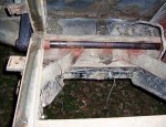
I did modify one crossmember slightly, just cut and bent the edge of one down some, and welded.

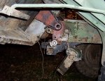
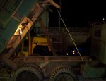
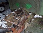
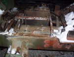
Got the pto, pto driveshaft, and hydrualic pump installed. Was going to install the tank and pump in the very back, but running the driveshaft was going to be a real pain. Wanted to keep the spare tire and air tanks in the orginal location, so to say the least, I didn't have much space left.

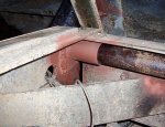
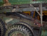
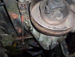
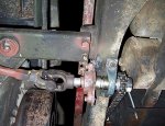
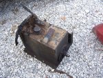
The tank has the pump inside of it. I put it next to the air tanks, inbetween the frame rails. Needed to chain drive off the pto driveshaft. The driveshaft has very tight clearences, had to grind the corners off the 7/8 square driveshaft to clear some bolts and braces. Also cut the ends off some bolts flush with the nuts.

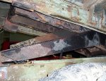
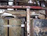
Made up a frame to fit around the tank, and used allthread to adjust it up and down for chain tension.

Had to get the right size yoke for PTO end of the driveshaft. Had to shorten the driveshaft some.

The tank barely fits under the bed, when the bed is down, it will fit inbetween the bed framerails, up into the bed crossmembers.

Still have to install hoses, cable for valve, shifter for pto, and taillights.

Very tight between the pto shaft and the spare tire, I may have to move the spare out a inch or 2. Modified the 4 bolt pillow bearing into a 3 bolt for a little more clearance.
 

Attachments

Last edited:

mangus580

New member
6,010
282
0
Location
Western NY
Got any more pics? I would like to see the tank too. I had to totally remove one of my x-members... My valve was mounted right to the cylinder, but I think I am gonna make a flange to attache hoses to the cylinder, and use a remote valve. Not happy with the current setup.
 

Stretch44875

Super Jr. Moderator
Super Moderator
Steel Soldiers Supporter
2,958
28
48
Location
Tiro, Ohio
The second pic from the bottom shows the top of the tank. Pump, valve, and tank are all one piece. There is a 1" shaft coming out the front of the tank, it drives the pump inside. Here is a pic of just the tank.

Yes, 8 degrees.... and dropping to 0 tonight, and 4-8 inches of snow tomorrow! That is pretty bad considering it is only early december, usually middle of janaury before the 0's hit.
 

Attachments

Last edited:
Top
AdBlock Detected

We get it, advertisements are annoying!

Sure, ad-blocking software does a great job at blocking ads, but it also blocks useful features of our website like our supporting vendors. Their ads help keep Steel Soldiers going. Please consider disabling your ad blockers for the site. Thanks!

I've Disabled AdBlock
No Thanks