• Steel Soldiers now has a few new forums, read more about it at: New Munitions Forums!

  • Microsoft MSN, Live, Hotmail, Outlook email users may not be receiving emails. We are working to resolve this issue. Please add support@steelsoldiers.com to your trusted contacts.


MEP 002A issues

hurst01

Member
76
1
6
Location
Jeffersonville, Indiana USA
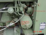
I have one of the MEP 002A Gensets that I have a few issues with. When I first bought this Genset I tried starting it only to find that the injector lines were disconnected. Further inspection revealed that the injector pump was stuck. I have a friend that has a MEP 002A that he suspected the transducer was bad. While waiting to repair the pump I left the Genset at his place. He switched the transducer and his is working fine.
Now to my problem. I rebuilt the injector pump and installed it. Starter won't turn when switch is in "START" position. It worked fine before the transducer was switched:?: I can jump the starter while someone holds the start switch on the START position and it starts fine. Is there something that my friend could have done while changing out the transducer? It cranked fine before. Does the start circuit run through the transducer?
Next problem. After starting, it doesn't have any output. I confirmed that all switches and breakers were in the correct position for power output. The Hobbs meter indicates 396 hours, the Genset hold excellent oil pressure and sounds really good.
Any help would be appreciated.

Ed
 

Speddmon

Blind squirrel rehabiltator
Super Moderator
Steel Soldiers Supporter
4,640
28
38
Location
Cambridge, Ohio
Do the fuel pumps come on when you turn the switch to the Prime/Run setting? If not, Check the DC circuit breaker right on the front panel beside the master switch.

If that breaker is "tripped" that would also explain the lack of generated power because that breaker supplies the 24 volts to the initial "flash" circuit of the field.

Probably need some more details about what actually does run or happen when you turn the switch to the various positions before any in depth troubleshooting can be done....but I would start with the breaker. The transducer should have no affect on the starting circuit, or power generation circuit (provided he hooked all of the wires back where they belong)
 

hurst01

Member
76
1
6
Location
Jeffersonville, Indiana USA
Hi Speddmon,
The pumps come on and build pressure as they should. When the start switch is hit the solenoid for the injector pump kicks on but nothing to the starter. The glow plugs heat also. The starter turns fine if manually jump across the solenoid and it starts as long as someone holds the start switch until the pressure builds up while jumping the starter.
What you mention about the 24v to flash the circuit makes sense. If you have any other ideas i would like to hear them.

Ed
 

Speddmon

Blind squirrel rehabiltator
Super Moderator
Steel Soldiers Supporter
4,640
28
38
Location
Cambridge, Ohio
if that's the case, it sounds like relay "k3" is not coming in. There is a "start disconnect switch" on the set somewhere. Don't ask me where...I'll go look here in a little bit. But if that switch is open, you'll get no power to the starter solenoid (The starter still will work if you jump across the solenoid though), and you'll not get the 24 volts to the "flash" circuit as well.

I'll check my sets out and try to find and take pictures of that disconnect switch for you, in the mean time read this thread, it will help to explain a little about that switch because truckfest was just asking about this the other day...MEP-003 start disconect switch.
 

Speddmon

Blind squirrel rehabiltator
Super Moderator
Steel Soldiers Supporter
4,640
28
38
Location
Cambridge, Ohio
Update for ya...the start disconnect switch is located right above the oil filter can, under a little metal cover (see picture). What I would do is take apart the connector for the two wires going to that switch, and take a small piece of wire, and jump the two wires going back to the control box together and try it again....if it tries to start then you have found your problem. Then it's time to dig into the switch and find out what's going on with it. The plunger that opens the switch comes through the backing plate and is operated somewhere inside the cover by the voltage regulator...I have no idea as to what operates this switch as I've never taken mine apart to look back there. And unless I have to, I'm probably not going to either...LOL.

If anybody has a good picture of the back side of this switch or what operates it, and how it operates I would appreciate knowing. If not, I'll figure it out when I need to take the fan shroud off of mine.

From your other post, I see that you had the IP off for repair, it's possible that when you had it off or were putting it back on, something caused that switch to open. Please keep me informed, as I get really curious as to what people found when digging into their stuff.
 

Attachments

hurst01

Member
76
1
6
Location
Jeffersonville, Indiana USA
OK, This is starting to make sense now. As you saw in the other post, I removed the Injector Pump to free the stuck plunger. I resealed it while I had it off. It looks as though it is extremely possible that the connection to the switch was disturbed in someway.
I certainly hope that this is the problem. I don't anticipate it being too much trouble to access the switch to check it out. I don't recall disturbing the wires to that switch, but I did take the connector loose just to the left side of the IP. I don't see it in the picture that you posted. It hooked to a connector right above and to the left of the IP and had several wires in it. One half was attached to something and pointed straight down. I used two fingers to plug it in and tighten it. I did disconnect it to make sure it was connected good with no bent pins. I don't have the generator here, it is still at my friends place. I will have to meet him when he gets off from work to check it out.
I am beginning to feel a bit better about this. I feared that the voltage regulator may have been bad for the output issue, but could not figure what the problem might be since it cranked before I removed the IP. I will let you know soon.

Thanks, Ed
 

hurst01

Member
76
1
6
Location
Jeffersonville, Indiana USA
I might ask another question while I am waiting to go take a look see at the switch. Is there some way of repairing the transducers? Anyone ever had one of them apart? I found one place that had one of them, or rather had access to one. After he added his price to it the cost of it was out of sight. He wanted almost $400 for it and suggested that I jump on it since it was the last known one in captivity. Got to be a way around it.
It was suggested to me that I buy a small meter that would check and adjust the frequency. I can't think what it was called now. I bought one but still would prefer to have it working correctly.

Ed
 

Speddmon

Blind squirrel rehabiltator
Super Moderator
Steel Soldiers Supporter
4,640
28
38
Location
Cambridge, Ohio
The connector you are talking about is what get's power to your glow plugs and the intake manifold heater. I believe that plug also feeds the voltage regulator and fuel stop solenoid as well....nothing that will keep it from starting though (Other than the fuel stop solenoid, but that is working since the set will start and run when you jump around the solenoid).

The transducers are nothing more than coil windings inside of a molded housing. What makes these difficult to find is the fact that they are all mounted in the same housing. Probably with a little research and ingenuity they could be replaced with something from the commercial market, but you would have a whole lot of time involved in cross referencing parts, studying the prints, and trying to find the # of winding turns and getting the right stuff. Then till you actually buy the stuff, you'll probably have almost $400 or more wrapped up in just purchasing the stuff.

There are others floating around out there...I have one, but the condition is unknown and the housing is cracked (Probably from someone dropping my parts set from a forklift, or otherwise just being extremely rough with it)

Edit; I just looked through the parts TM, and the front transducer (there are two CT's in the control box) is the same on both the MEP-003a and MEP-002a. However the rear one is different. I have the MEP-003a's so mine are a little different.
 
Last edited:

hurst01

Member
76
1
6
Location
Jeffersonville, Indiana USA
Well, I went to check out the generator today. It was the starter switch by the fuel shut-off solenoid. It is under the small tin cover with the wing nut holding it on. I took the cover off and tried cleaning the contact. The started engaged and turned for a bit and would not turn any more. I pushed the contacts together with my finger while reaching around to apply the starter switch. It not only turned but started. It produced voltage like it should.
I shut it down and it would not turn again. I removed the switch from the base. The contacts are burned a bit but the outer half of the contact is bent and won't stay engaged. It appears that someone has had it apart before because the adjustable outer contact is bent enough that it doesn't make contact. I removed it and brought it home.
Looking at it, it may be a pain to adjust. The outer contact is a thin strip of copper and the way it is bent it is going to be hard to straighten it. I may have to drill out the rivets and remove the outer contact in order to straighten it. I can install it again by using screws. The outer copper arm is very flimsy is very touchy .
I am having great difficulty holding my eyes open so most of this won't make sense. More to come tomorrow.

Ed
 

mistaken1

New member
1,467
6
0
Location
Kansas City, KS
Well, I went to check out the generator today. It was the starter switch by the fuel shut-off solenoid. It is under the small tin cover with the wing nut holding it on. I took the cover off and tried cleaning the contact. The started engaged and turned for a bit and would not turn any more. I pushed the contacts together with my finger while reaching around to apply the starter switch. It not only turned but started. It produced voltage like it should.
I shut it down and it would not turn again. I removed the switch from the base. The contacts are burned a bit but the outer half of the contact is bent and won't stay engaged. It appears that someone has had it apart before because the adjustable outer contact is bent enough that it doesn't make contact. I removed it and brought it home.
Looking at it, it may be a pain to adjust. The outer contact is a thin strip of copper and the way it is bent it is going to be hard to straighten it. I may have to drill out the rivets and remove the outer contact in order to straighten it. I can install it again by using screws. The outer copper arm is very flimsy is very touchy .
I am having great difficulty holding my eyes open so most of this won't make sense. More to come tomorrow.

Ed
Tomorrow never came! :razz:

Were you able to repair this part?
 

hurst01

Member
76
1
6
Location
Jeffersonville, Indiana USA
Oh! Sorry. I took the cover off the switch and under the cover is something very similar to a set of ignition points It is adjustable but pretty flimsy. Someone had apparently tried to adjust it before by bending it (several times). I tried bending it back into shape with no success.
It is a very thin strip of metal that has a set of contacts on the end. It is riveted to what I believe was an insulator. It was bent at one of the rivets. My thought was to drill out one of the rivets, straighten the piece and rivet it back.
After I got it out of the piece that it is mounted in I was able to carefully place a small blade of a screwdriver under the strip close to the rivet and then with a small pair of pliers, bend it back close enough to it's original shape that it had the right tension on it so it could be adjusted.
The problem is that the more that I tried to straighten it while mounted on the switch, it would bow and cause the contacts to not align correctly. Once I was able to get to it to get it relatively straight the contacts would align again. I took an ignition points file and dressed the contacts up and then cleaned them up with contact cleaner.
The way the switch works is, not only does it make contact for the starter, It also makes contact and "excites" the generator so it will charge. Once it starts there is a fiber pin that pushes the contacts apart, much like a fiber pin that opens a set of ignition points.
I owe Speddmon many thanks for helping me with it. He suggested that the switch might be the problem and it was. The part can be removed from the switch assembly without removing it. Just be extremely careful because it is delicate. When adjusting the contacts they should be set to where they will open when it starts. Don't go overboard. It should have the minimum amount of movement.
Sorry about not completing the post.
 

mistaken1

New member
1,467
6
0
Location
Kansas City, KS
Thank you for the report. It is good to know it can be repaired.

The reason I ask is I now have one of these generators. It may fire right up and produce power or there may be issues. So I have been here researching ahead of time when I came across your post. I hope have time to work on the generator this coming weekend.
 

Speddmon

Blind squirrel rehabiltator
Super Moderator
Steel Soldiers Supporter
4,640
28
38
Location
Cambridge, Ohio
The connector you are talking about is what get's power to your glow plugs and the intake manifold heater. I believe that plug also feeds the voltage regulator and fuel stop solenoid as well....nothing that will keep it from starting though (Other than the fuel stop solenoid, but that is working since the set will start and run when you jump around the solenoid).

The transducers are nothing more than coil windings inside of a molded housing. What makes these difficult to find is the fact that they are all mounted in the same housing. Probably with a little research and ingenuity they could be replaced with something from the commercial market, but you would have a whole lot of time involved in cross referencing parts, studying the prints, and trying to find the # of winding turns and getting the right stuff. Then till you actually buy the stuff, you'll probably have almost $400 or more wrapped up in just purchasing the stuff.

There are others floating around out there...I have one, but the condition is unknown and the housing is cracked (Probably from someone dropping my parts set from a forklift, or otherwise just being extremely rough with it)

Edit; I just looked through the parts TM, and the front transducer (there are two CT's in the control box) is the same on both the MEP-003a and MEP-002a. However the rear one is different. I have the MEP-003a's so mine are a little different.

I don't know what I was thinking and/or drinking when I wrote that statement. The CT/CVT assemblies are exactly the same for the MEP-002a's and the MEP-003a's There is a different one for the 400 Hz models vs. the 60 Hz models, but the 60 Hz 5 KW and 10 KW assemblies are the same.
 

FlyingFox

New member
2
1
1
Location
Paauilo, Hawaii
MEP002A phase selector switch

I don't know if I'm in the right thread or not since this is my first post. I have a wide selection of trucks and generators that I picked up as a package deal. We use them in a reforestation project on the Big Island of Hawaii. Recently we started restoring an MEP-002A genset. It had a stuck phase selector switch. We got a new one from Green Mountain Generators, but it is a slightly different connector arrangement. The one on our generator is P/N 123919LA and the new one is P/N 123919LB. Does anyone know how to hook up the LB switch on a genset that had a LA switch. I haven't been able to locate a wiring diagram that shows the corresponding connectors. Most are the same, but there is enough difference that I don't want to get it wrong. Any guidance will be greatly appreciated.
 

Guyfang

Moderator
Staff member
Moderator
15,861
22,044
113
Location
Burgkunstadt, Germany
Do you have the TM's downloaded for the MEP-002A and MEP-003A, that are in the TM forum of Steel Soldiers? If not, download them.

In TM5-6115-585-34, (yes I know it is the MEP-003A book, but it's the same are the 002A book, and the printing is better) on PDF reader page 94 is some info over the two switches. Then go to PDF reader page 101 and you will find some more info on the S6 switches. Both switches work for your gen set, but you need to move some wires around to make it fit. Then turn to PDF page 39, to see the schematic. On the schematic is the connections and wire numbers for the S6.
 
Last edited:

FlyingFox

New member
2
1
1
Location
Paauilo, Hawaii
MEP002A phase selector switch

I found a chart of the two switches on page 6-16 in TM 5-6115-584-34, but the contacts listed for the 123919LB are not correct. If you match up the sections between the two switches by contact you will notice that the LB switch has the contacts wrong for the wiring diagram to the left. I have corrected all of this and I think I'm on the right track. I'll look at the manuals and sections you listed as well. Thanks for the help. I'm not sure how to insert attachments, but I have a spreadsheet showing the correspondence between sections of the two switches and an annotated version of the contact chart.
 
Last edited:
Top
AdBlock Detected

We get it, advertisements are annoying!

Sure, ad-blocking software does a great job at blocking ads, but it also blocks useful features of our website like our supporting vendors. Their ads help keep Steel Soldiers going. Please consider disabling your ad blockers for the site. Thanks!

I've Disabled AdBlock
No Thanks