Great Peashooter...that's just what I needed...thanks. I'll plan for modification of the pin.
I'd be worrying more about capacity of the MC going to the 1 1/2" if I were not going to 4x4. That should not be a problem.
Since I have never had the deuce apart to see, the pin has a center that fits the cup on the 37317 (in the links) but the standard cup for the 1 3/8 size is flat inside. How does the pin stay centered in the flat cup?
Attachments
-
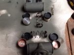 73.2 KB Views: 32