• Steel Soldiers now has a few new forums, read more about it at: New Munitions Forums!

  • Microsoft MSN, Live, Hotmail, Outlook email users may not be receiving emails. We are working to resolve this issue. Please add support@steelsoldiers.com to your trusted contacts.


re-wiring my MEP-004a for different voltages, including single phase

sewerzuk

Member
524
9
18
Location
Seaside, OR
Did the planned mods to the Control Transformer to make the overload trip properly work out?
Kind of; they accomplished the goal of lowering the ammeter and % power meter readings, and raising the trip setpoints for the overloads. But...it was a little too much. The meters began to read about 10% too low, which I'm really not a fan of. I decided (for now) that the best thing to do is to leave them as is and just know that it is OK to run things right up to 120-130%.

On a side note, I have replaced 2 of the CT's before (the one further away from the reconnection board) on -004's. I could have swore that they had 4 turns going through them; removing one turn should adjust the setpoints by about 25% (which was my goal). The only one I currently have in my shop only had 3 turns (which is why it moved the setpoint too far). I have verified that the ammeter works properly (against my clamp-on ammeter). Maybe I'm just remembering wrong, but could somebody check their -004/005 and see how many turns each lead takes through the CT? If you have one that takes 4 turns, removing 1 turn would likely work out fine...
 

sewerzuk

Member
524
9
18
Location
Seaside, OR
Here is the new updated video, complete with the modifications to the underside of the reconnection board:

[media]http://www.youtube.com/watch?v=YmF4Awr3uc4[/media]
 

sewerzuk

Member
524
9
18
Location
Seaside, OR
The video I posted should be easy enough for just about any average wrench turner to follow; I do plan on doing some modifications to the CT in mine to change setpoints and meter readings. After some thought, I believe that it will be much easier to add appropriately sized resistors inline with the secondary side of the CT windings. This is not only easier than removing one turn, it allows for a quicker changeover back to 3 phase as well.
I will also change out the cables for L1 and L3 to compensate for the additional current.

I'll post additional pictures, test results, etc. here as time goes on. For the next week or two I have other projects requiring my attention...there are a set of deuce axles spread out all over my shop floor that need reassembly!
 

ctfjr

Member
81
0
6
Location
central CT
I will also change out the cables for L1 and L3 to compensate for the additional current.

Sewerzuk I have followd your posts religiously and am thinking about getting an 004 or 005 to convert as a project. A big thanks for all the info you have posted - not the least is the videos.

I have one question tho. After you convert, say the 004 to single phase, is the wire size big enough to handle the additional current? Do you have any idea what gauge the wires are that come out to the connection strip?
 

Motownmike

New member
20
0
0
Location
Mid Michigan
My Connection Board

Sewerzuk, I went out and started the conversion tonight. My set seems a little different than yours, my buss bar is bolted underneath, it's going to be a pain to cut it. If I remember correctly yours is on top of the board. I took a couple of pics to show everyone.
Thanks again for the videos and hard work to figure this out.
Mike
 

Attachments

Ken_86gt

Member
428
2
18
Location
Williamsburg VA
My set seems a little different than yours, my buss bar is bolted underneath, it's going to be a pain to cut it.
Mike
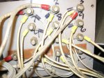
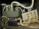
When I did mine, its a MEP-005A, I cut the bus bar on the bottom where ALL of those wires are.... I removed some and pushed some out of the way- and then used a Dremel tool with a very small cut off disk to cut the bus bar in place, I just removed the small picece from the T12 area. I broke 2 or 3 of the disk's before I was done. I attached the jumper wire on the bottom as well. Go back and look at the original link I posted to see the pictures of this.
 

Motownmike

New member
20
0
0
Location
Mid Michigan
Ken, that's what I was planning to do, I just have to find my Dremel tool!
Thanks for the generator tutorial at your webpage, I don't have enough time this morning to go over it all, it will have to wait for work.
Mike
 

sewerzuk

Member
524
9
18
Location
Seaside, OR
I have seen them on both top and bottom; the last batch of -004's I got were all on top. I honestly haven't looked closely enough at prior sets to know where the bars "usually" are...seems there are quite a few with the bars on bottom.

There are certainly more professional-looking ways to accomplish this; complete with a custom length jumper, reconnections on the bottom of the board, etc. The method I used showed well on the video :)
My thought was that if somebody is accomplished enough to follow the video and duplicate the procedure, they will also be able to modify it to make their conversion better suited to your specific situation. If you come up with a better idea, post it up!

A few ideas/thoughts/plans I had:

The conversion back to 3 phase is a little more complicated now; X12EG16N can stay on the T11 (or T10 or T13, wherever you moved it to), but the other leads may need to be moved back to their original locations. I'll do some additional reading to find out if they are OK to leave in their new positions. If not, it might be nice to mount a terminal board somewhere inside of the generator and run jumper wires to both locations; then you could simply move the leads from one terminal to the other each time a switch from single to 3 phase takes place. Even cooler would be a 2 pole switch.

If conversions between single and 3 phase will be commonplace, it would be advantageous to leave the jumper on top of the reconnection board, so that the board doesn't need to be removed for each changeover.

I plan to mount a terminal board somewhere in the generator (possibly epoxied to the top of the first CT) with resistors wired in for both single and 3 phase operation in line with the secondary sides of the CT. That way, I can easily swap between the 2 overload setpoints and meter ranges. I have yet to load the generator and determine which size/power resistors to use...but that will happen in the near future. Even cooler...a 3 pole switch!

I plan to replace the L1 and L3 cables going from the reconnection board to the main breaker, and from the main breaker to the load terminals with something a few sizes larger than what is already in there (I'll probably use 6ga cable because I have a lot of it, and it is good for 101A in chassis wiring). Although the cable that is in there appears to be of high quality and is probably OK for the higher current in single phase...I feel better about upsizing it a little.

I also plan to fully load the generator and then use my ammeter to test the currents flowing through each individual generator lead. I'm interested to know how (or if) unbalanced the current flow is. I've mulled it over and over in my head and just haven't decided whether or not the current is unbalanced. As an ex-Navy ET, I SHOULD know the answer but rather than spend any more time trying to think about it, I'll just fire up the Fluke and get a solid answer :beer:
 
Last edited:

sewerzuk

Member
524
9
18
Location
Seaside, OR
I had a little time last night to mull over the schematics and I came to a couple of conclusions:

We moved 3 leads under the recon board to bring voltages back to normal; X8HH16B from T8 to T11, X8A16B from T8 to T3, and X12EG16N from T12 to T13.
When converting back to 3 phase 208, X8A16B can remain on T3 and X12EG16N can remain on T13 (or T11 or T10, depending on where you put it). But, X8HH16B will need to go back to T8. I haven't tested this theory, but looking at the schematics, it appears that the voltages will be OK for the first 2, but X8HH16B will supply improper voltages to the voltage regulator. It MIGHT work just fine if left in place, but I wouldn't bet on it...and I really don't want to test it on mine because I think I stand a good chance of damaging something.
When converting back to 3 phase 417v, X8A16B and X8HH16B both must go back to T8; otherwise you will be supplying a VERY high voltage to components inside the control cubicle...

I spent some time looking at it, and I don't believe there is any connection that allows you to leave these leads in one place for all 3 configurations. The best option for a quick changeover is an external terminal board or a 2 pole double throw switch.
 

sewerzuk

Member
524
9
18
Location
Seaside, OR
Since it was such an amazing day here in the NW (68 degrees and not a cloud in the sky!), I wheeled the -004 outside and hooked it up to the load bank. I adjusted it for a steady 50A load single phase, and then used my clamp-on ammeter to check each of the generators 12 leads. Current flow through every lead was roughly 25A; this means that, despite looking funny on paper, zigzag is truly a balanced configuration. We are not placing any more load on individual windings in single phase than we do in 3 phase.
On to CT current measurements...
 

PeterD

New member
622
6
0
Location
Jaffrey, NH
Personally I think I'll do a terminal strip instead of a switch, but do you have any idea of the currents drawn in those three leads? A three position double throw switch is not uncommon, and would be a faster way (does anyone care about fast, I probably would not go back to 3 phase very often at all...)


Tlauden

Member
840
3
18
Location
Halifax Pennsylvania
Wow, after reading this thread I am more lost than I knew possible...

My hats off to all you who know about electricity and how to make these gensets work out for ya. If I ever get one I now know who to ask for help!!
 

sewerzuk

Member
524
9
18
Location
Seaside, OR
All sorts of data!

Hooked up my ammeter and voltmeter to the secondary side of the CT and got some good numbers. There were actual measurements:


.65A (CT secondary)
5.61V (CT secondary)
100% (% power meter)
46A (clamp on ammeter reading to load bank)

.73A (CT secondary)
6.1V (CT secondary)
110% (% power meter)
51A (clamp on ammeter reading to load bank)

0.90A (CT secondary)
7.65v (CT secondary)
135% (% power meter)
63A (clamp on ammeter reading to load bank)

Checked the math and it appears that those are almost perfectly linear numbers...so a simple resistor inline with the CT secondary should adjust meter readings and trip setpoints with no problem.

Looks like I'll need a minimum 7 watt resistor at about 2.25 ohms. Couldn't find anything in stock anywhere at 2.2 ohms, but I did find a 10W 2 ohm one. Should be close enough...those meters and trip setpoints aren't very accurate anyway. Here are the resistors I ordered:
Digi-Key - RHRB-2.0-ND (Manufacturer - RH0102R000FE02)
And the terminal block:
http://search.digikey.com/scripts/DkSearch/dksus.dll?Detail&itemSeq=110281088&uq=634639802343815077

Since this is a 2 ohm resistor, my meters will read a little bit too high, and my trip setpoints will be a little too low. No problem with being a little bit conservative...but it will definitely allow me to pull 15kW sustained with no trip, and the meters will be very close to accurate.
 

PeterD

New member
622
6
0
Location
Jaffrey, NH
All sorts of data!

...

Looks like I'll need a minimum 7 watt resistor at about 2.25 ohms. Couldn't find anything in stock anywhere at 2.2 ohms, but I did find a 10W 2 ohm one. Should be close enough...those meters and trip setpoints aren't very accurate anyway. Here are the resistors I ordered:
...
Some alternatives are either to custom wind your own resistors, use an adjustable resistor (those are available as needed, but not as common as they were years ago) and to use a combination of parallel and series resistors to get the desired value(s) and wattage. I can help with the math for wattage and values if anyone wants an assist there.
 
Top
AdBlock Detected

We get it, advertisements are annoying!

Sure, ad-blocking software does a great job at blocking ads, but it also blocks useful features of our website like our supporting vendors. Their ads help keep Steel Soldiers going. Please consider disabling your ad blockers for the site. Thanks!

I've Disabled AdBlock
No Thanks