• Steel Soldiers now has a few new forums, read more about it at: New Munitions Forums!

  • Microsoft MSN, Live, Hotmail, Outlook email users may not be receiving emails. We are working to resolve this issue. Please add support@steelsoldiers.com to your trusted contacts.


re-wiring my MEP-004a for different voltages, including single phase

sewerzuk

Member
524
9
18
Location
Seaside, OR
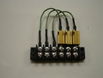
I might be a little off here (I often am) but I believe that, since the value of the resistor that I chose was roughly 10% lower than whet I needed, the meters/trip setpoints will remain 10% of the difference (10% of 35%) off. This means that when the generator is operating at actual 100% power, the % power meter will be reading 103.5%. I'm really not worried about it, since the scale is graduated in 10% increments. 3.5% is less than 1/2 of one graduation.
Most of the time, the sets I test are off anyway...some by as much as 10-15%.

I'll know for sure in a week or two; should be less than 1 hour to get it all installed.
 

Motownmike

New member
20
0
0
Location
Mid Michigan
Flawless....

Hey Sewerzuk, I finished the conversion last Saturday, everything worked out perfectly. I ended up spending more time cutting that dog-gone bussbar than I wanted to because I couldn't find my Dremel tool.
I still have an issue with flashing the field, but it's all oil pressure related. I ended up starting the set without flashing the field. I let it warm up, shut it off and restart while flashing the field. The oil pressure rises quickly this way and I can flash it normally by holding up the start switch. I can't seem to get past my reluctance to hold that start switch up till the oil pressure rises from a cold start.
It could be normal or I have a lazy pressure sensor, not a show stopper by any means.
I think it will be a couple of months before I can get a suitable load-bank cobbled together though.
Thanks again for all your help and also this site!
Mike
 

sewerzuk

Member
524
9
18
Location
Seaside, OR
I can't seem to get past my reluctance to hold that start switch up till the oil pressure rises from a cold start.
I had the same reluctance with my first MEP! In fact, I actually planned to add a couple of time delay relays so I wouldn't have to hold the switch in start so long after the set actually started.
I have gotten used to it now, though. Your speed switch should disengage the starter motor almost immediately after the engine starts, so you shouldn't worry too much about holding the switch. If you DO hear grinding, its time to look at your speed switch...
On a cold set, I often have to hold the switch in start for several seconds after the set has come up to speed to allow oil pressure to build up. I'm betting your oil pressure switch is just fine.
I believe the tech manual actually says that it is permissible to hold the start switch in start for up to one full minute with the engine running (its a vague memory though...I might be off).
 

PeterD

New member
622
6
0
Location
Jaffrey, NH
... I let it warm up, shut it off and restart while flashing the field. The oil pressure rises quickly this way and I can flash it normally by holding up the start switch...

Why shut it off, while running you should without any problems be able to push the start switch up and flash. If it grinds when you do that then the speed sensor (intake side of the engine) is not working correctly.

Best is to just force yourself to do it the 'right' way (hold the switch in start until voltage and frequency read) and I'm sure you will do OK.
 

rogersn67

New member
84
6
0
Location
Bryn Mawr, Pa
Thank you for all of the work you have done, and sharing it with everyone here. You have saved me the time and effort of trying to figure this out myself....
 

sewerzuk

Member
524
9
18
Location
Seaside, OR
Well...the resistors and terminal board showed up on Friday. I dove into the project this afternoon...pretty simple little mod...under an hour to make all of the connections. It didn't work :doh:

Well..the theory was sound, anyway. Its just that my resistor values were WAY off. I still don't know why. They were dropping about 1.8v under full load...which is almost exactly the amount I was aiming for (which means that my math was correct). But, for some reason, that didn't change the meter readings or trip setpoint. Obviously, there is something at play in that circuit that I didn't grasp...

I had a pile of 1 watt resistors with varying values from various projects, so I just began swapping them in to see what would happen. A 1 watt resistor dissipating 7 watts lasts for about 15 seconds before it burns up. Fortunately, resistors are inexpensive and I had a lot of them. The 50 ohm resistors I had were the closest to what I need; they seemed to drop the meter readings about 20%. I need a little more than that...so I ordered some 10 watt 75 ohm resistors. The waiting game resumes....hopefully they'll be here by next weekend. That should be just enough time to clear all of the crispy electronic smell out of my shop [thumbzup]

Unfortunately, I couldn't test to make sure that the 50 ohm resistor also dropped the overload setpoint because they don't last long enough. I will have to verify that after I get the new batch of resistors...
 

Attachments

sewerzuk

Member
524
9
18
Location
Seaside, OR
I've been mulling this over as I work on another project...and I think I had a conceptual error on how the CT works.
I had based my little resistor network assuming that the CT produced a voltage that related to the amount of current flow through the 12 leads...and that voltage was what was measured to drive the meters.
Instead, I believe that it produces a current proportional to the current flowing through the 12 leads...
I fired the set back up and took a voltage across the secondary windings of the CT with my resistors still in place and, sure enough, the voltage had increased by the exact amount that the resistors were dropping. If I put a bigger resistor in there, the voltage will just keep getting higher.
Instead, I believe I need to shunt some of the current across the windings to reduce the amount that flows through the LMU and thermal watt converter. Based on the current readings I took before I installed the resistors, a 40 ohm resistor across the secondary of the CT should do it. But, to keep it safe, I plan to start high and work my way down. Don't want to burn up that CT...

Edit: Thanks Ken_86gt for your thoughts on this.
 
Last edited:

sewerzuk

Member
524
9
18
Location
Seaside, OR
Got it!

I had a few minutes to drop some of those 50 ohm resistors across the secondary side of the CT; it worked out perfectly!

According to the math, a 38 ohm resistor is the ideal size (a 40 ohm would be just about perfect). That would drop the meter readings by about 35%. Since all I had were 50's, that is what I used. They dropped the percent current and percent power meter readings by about 20%; not quite enough, but enough that the trip setpoint is now around 18kW. So, even though they are still reading a little bit too high, I can pull 18kw all day long in single phase.
I load tested it at 70 amps (almost 17kW) for about 30 minutes with no issues.

I shot some video of the mod; I hope to get a chance to edit and upload it this evening.

This little tweak completes the single phase experiments/modifications. That's it! The set is now an honest 15kW single phase 120/240 generator...

:grd:
 

Attachments

kgblazerfive

New member
8
1
0
Location
Hooper,UT
My issue with these blasted things is it will work some times and some times it will not. as far as generating anything at this point. Some times I have to hold the start switch up for like 10 minutes then it will start generating other times nothing. I really want to change it to 120 but it seems like it would be a waste unless I can figure out this other issue.

It is almost like I have a $1200 diesel engine that I own, ready to shoot it and buy a 002 instead of the 004 that I have.
 

sewerzuk

Member
524
9
18
Location
Seaside, OR
My issue with these blasted things is it will work some times and some times it will not. as far as generating anything at this point. Some times I have to hold the start switch up for like 10 minutes then it will start generating other times nothing. I really want to change it to 120 but it seems like it would be a waste unless I can figure out this other issue.

It is almost like I have a $1200 diesel engine that I own, ready to shoot it and buy a 002 instead of the 004 that I have.
I'd guess that something isn't working in the field flash circuitry. A relay, or maybe even one of the gangs on the start switch.
 

trukhead

New member
725
5
0
Location
dane/wi
Ok, I have been followiong these threads and found them fascinating. My wuestions are:

Since these units make 3 phase, does the conversion separate the legs into 1-2 and 2-3 to make single phase exclusively?

does it make nonsense to use an oo4 as a backup for a house that may only use 4kw but have the big capacity to make the well pump intermittently?

or does it makes sense to run an 003 or go to a 002 at capacity with some intermittent overload? 4 kw + intermittent 2kw overload?:shock:
 

PeterD

New member
622
6
0
Location
Jaffrey, NH
Agreed, a 003 might be a much better choice. My use of the 004 is based on having electric heat, (basically an all-electric home) and a large power requirement, and even with heat on I don't reach anywhere near what the 004 can put out.
 

trukhead

New member
725
5
0
Location
dane/wi
Truckhead I would think a MEP003a would be more than enough for you.
Agreed, a 003 might be a much better choice. My use of the 004 is based on having electric heat, (basically an all-electric home) and a large power requirement, and even with heat on I don't reach anywhere near what the 004 can put out.
Gotcha, Thanks for the advice! 003 seems to make much more sense to run a smaller unit nearer to capacity with minor intermittent overload.

I became aware of the phase conversion on one of these threads. Does the 003 have a need for phase conversion?

I see them listed as 3 phase as well as single phase.

Is the generation of 3 phase current diminishing the capacity of single phase current or is just the tapping off of single phase, by nature just less efficient?

fascinating thread!:cool:
 

sewerzuk

Member
524
9
18
Location
Seaside, OR
Gotcha, Thanks for the advice! 003 seems to make much more sense to run a smaller unit nearer to capacity with minor intermittent overload.

I became aware of the phase conversion on one of these threads. Does the 003 have a need for phase conversion?

I see them listed as 3 phase as well as single phase.

Is the generation of 3 phase current diminishing the capacity of single phase current or is just the tapping off of single phase, by nature just less efficient?

fascinating thread!:cool:
-002 and -003 are selectable between single and 3 phase with one switch; its a pretty neat feature!

It isn't an efficiency issue; it is the limit of how much current each individual winding can carry. When pulling single phase off of a wye (3 phase) configured machine, you are pulling more current through individual windings than when the machine is configured for single phase.
 
Top
AdBlock Detected

We get it, advertisements are annoying!

Sure, ad-blocking software does a great job at blocking ads, but it also blocks useful features of our website like our supporting vendors. Their ads help keep Steel Soldiers going. Please consider disabling your ad blockers for the site. Thanks!

I've Disabled AdBlock
No Thanks