• Steel Soldiers now has a few new forums, read more about it at: New Munitions Forums!
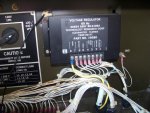
  • Microsoft MSN, Live, Hotmail, Outlook email users may not be receiving emails. We are working to resolve this issue. Please add support@steelsoldiers.com to your trusted contacts.


10 kw generator mep 803a

jbk

Member
404
5
16
Location
livingston la.
thier was a bullitin on the 5 and 10 kw tqg sent to all services a few years back. i have it stored somewhere just couldnt find it tonight. the problem was with the a1 bridge rectifier circut. if the gen. is held in the start position to long voltages can peak at over 400 vac across the quad winding circuit. this can cause the diodes to short wrecking the voltage regulator and stator. the fix is a fuse 3 amp. 250 vac slow blow. install the fuse between terminal 8 of the a1 voltage rectifier and the q1 quad winding circuit. easy fix dont know if the problem was corrected in later generators. found the document
 

Attachments

Last edited:

ETN550

New member
457
9
0
Location
Knoxville, TN
thier was a bullitin on the 5 and 10 kw tqg sent to all services a few years back. i have it stored somewhere just couldnt find it tonight. the problem was with the a1 bridge rectifier circut. if the gen. is held in the start position to long voltages can peak at over 400 vac across the quad winding circuit. this can cause the diodes to short wrecking the voltage regulator and stator. the fix is a fuse 3 amp. 250 vac slow blow. install the fuse between terminal 8 of the a1 voltage rectifier and the q1 quad winding circuit. easy fix dont know if the problem was corrected in later generators. found the document
JBK,

Thanks for posting this. Just found this article and will be obtaining the parts for an un-modified 802A. Fortunately, the set I'm working on seems okay and does start quickly. I do release the start switch as soon as I see the voltage rise but the needle is so fast it can peg the meter. Is there any way to determine if the A1 in my set has been upgraded with the permanant fix they talk about in the article?

Also, what is the black wire in your photo that goes through the square hole on the left above the A1 with the sealant around it?

Thanks,
Doug
 

ETN550

New member
457
9
0
Location
Knoxville, TN
My Version of the Fuse Modification

I installed the the 3 Amp slow blow fuse today in order to protect the quad winding in the stator per the service bulletin.

Instead of using an inline fuse holder I bought a 4 place holder and pop riveted it to the floor in the control box.

After cutting all the tie wraps from the wire on terminal #8 I traced it back to the J5 plug. I cut it a few inches off the plug and installed a spade connector. I then installed a spade connector on the other end and the resulting wire length was the perfect length to run it back to the #8 terminal along a slightly different route, thus retaining the original wire with no additional wire.

I inserted spare fuses in the holder's 3 unsused sockets.

The spade connectors can reach any of the 4 fuse locations so if a fuse does blow I can simply move the spade connectors to a fresh fuse!

DSCN3265.jpg
 
Last edited:

Speddmon

Blind squirrel rehabiltator
Super Moderator
Steel Soldiers Supporter
4,640
28
38
Location
Cambridge, Ohio
Nice work.

Someday I'll get me an 803a....probably when the military is finally getting rid of them and the prices come down cause I'm a cheapskate...LOL
 

rjbguns00

New member
23
0
0
Location
Cedar Park, Tx
thier was a bullitin on the 5 and 10 kw tqg sent to all services a few years back. i have it stored somewhere just couldnt find it tonight. the problem was with the a1 bridge rectifier circut. if the gen. is held in the start position to long voltages can peak at over 400 vac across the quad winding circuit. this can cause the diodes to short wrecking the voltage regulator and stator. the fix is a fuse 3 amp. 250 vac slow blow. install the fuse between terminal 8 of the a1 voltage rectifier and the q1 quad winding circuit. easy fix dont know if the problem was corrected in later generators. found the document

Does this apply to the MEP-002As as well?
 

Speddmon

Blind squirrel rehabiltator
Super Moderator
Steel Soldiers Supporter
4,640
28
38
Location
Cambridge, Ohio
You ,missed the next couple of letters..."5 and 10 kw tqg". The tqg stands for "Tactical Quiet Generator", the 002/003 gennys are far from quiet...LOL The voltage regulators are totally different animals between the much older 002/003 series and the newer 802/803 series gennys
 
Last edited:

bullwhacker

New member
20
0
0
Location
san jose calif
I am curious?
The fuse mod mentioned is for just the mep802a?
I just got a mep803a TQG and from what I read it has a crank sensor to detect engine speed and a preset point and disengages the starter?

I also have a problem where the CB1 breaker pops as soon as yo turn the master switch from off to prime then start.
The maint. crank switch works and I can crank it and set back to normal.
I read it is for the "DC" circuits and need to know which ones are those?
I have a "manual" I downloaded and it is basically a operation and maint. manual; not a service one that would show a genset tear down and repair.
The motor like like it is new? Fresh paint and all shiny on it. No rust on the genhead etc..20130924_125654.jpg20130924_125712.jpg20130924_125732.jpg20130924_125756.jpg20130924_125806.jpg20130924_125837.jpg20130924_125856.jpg
 

bullwhacker

New member
20
0
0
Location
san jose calif
24v jumper

Today I was able to start the engine. I had to disconnect the fuel pump lead 24v and run a jumper from the hot and neg on the starter. I powered the pump and it worked; I then used the dead crank switch to turn over the motor while holding the engine stop arm back on the pump. Engine fired up and all looks and sounds normal. Didn't run it long and shut it down. Not to find out what and where is the DC power control items and trace to what is causing the CB1 breaker to trip as soon as I turn the master switch on. Before that the panel lights work fine.

I am curious?
The fuse mod mentioned is for just the mep802a?
I just got a mep803a TQG and from what I read it has a crank sensor to detect engine speed and a preset point and disengages the starter?

I also have a problem where the CB1 breaker pops as soon as yo turn the master switch from off to prime then start.
The maint. crank switch works and I can crank it and set back to normal.
I read it is for the "DC" circuits and need to know which ones are those?
I have a "manual" I downloaded and it is basically a operation and maint. manual; not a service one that would show a genset tear down and repair.
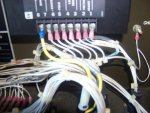
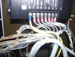
The motor like like it is new? Fresh paint and all shiny on it. No rust on the genhead etc..View attachment 455058View attachment 455059View attachment 455060View attachment 455061View attachment 455062View attachment 455063View attachment 455064
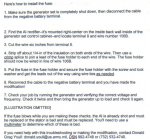
 

ETN550

New member
457
9
0
Location
Knoxville, TN
Fuse mod is for the 803A as well as the 802A. Highly recommend it to avoid having to replace the generator end due to control overload. Easy mod.
 

bullwhacker

New member
20
0
0
Location
san jose calif
Fuse mod is for the 803A as well as the 802A. Highly recommend it to avoid having to replace the generator end due to control overload. Easy mod.
Thanks will make the mod.
I know it has most likely mentioned before where can I find the procedure to test the voltage reg. to see if it is blown and if it is blown the stator leads and what to do to see if they are shorted?
I have included a picture of the panel opened and I found on the blue colored master switch some one has made two jumper on the top and bottom leads to the top and bottom in the back?
Those are the red and black wires?
I disconnected one side of those two jumpers and still have the breaker tripping propblem.
The CB1 breaker trips as soon as the master switch it turned from off to any other position.
From what I can figure that goes to the DC Circuits? If so what are those circuits?
The panel lights work before the switch is turned.
The FU1 fuse is okay and again from what I can figure goes to the Alt. charging system?
I checked the Fault Breaker left side next to the panel (left side of picture you'd see that white arrow with "test" ) and found a built-in little breaker rocker switch inside the control panel cavity on the breakers side?

20130928_154745.jpg


I tried to trip that and it will not move; frozen like?
I wouldn't be asking all these questions if I could find the service manual where wiring is shown, etc..
I also saw a "diagnostic" plug on the generator on the panel side. What kind of "panel" is hooked to that and would you know the name and part number?
Also I did the "sniff" test around the panel and gen head and didn't smell or see anything burnt.
 
Last edited:
Top
AdBlock Detected

We get it, advertisements are annoying!

Sure, ad-blocking software does a great job at blocking ads, but it also blocks useful features of our website like our supporting vendors. Their ads help keep Steel Soldiers going. Please consider disabling your ad blockers for the site. Thanks!

I've Disabled AdBlock
No Thanks