• Steel Soldiers now has a few new forums, read more about it at: New Munitions Forums!

  • Microsoft MSN, Live, Hotmail, Outlook email users may not be receiving emails. We are working to resolve this issue. Please add support@steelsoldiers.com to your trusted contacts.


2008 M1083a1 no 24v on gauge or charging

jth3rd

Member
87
30
18
Location
elk city , oklahoma
9 months of waiting and finally got my m1083 home and sf97 in.
Very happy felt like a little kid driving it around
But I'm needing some help if you dont mind getting everything straighted out on it


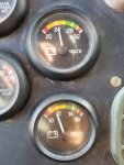
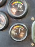
24v system doesnt registrator on the gauge. Checked power at the batterys and doesnt show a charge 19-20v on meter with truck running, alternator shows flashing green on both leds.


Speedo doesnt work mileage shows and back lighting works. And abs light is on probably cause of the issue with the speedo.. is the speedo run on 24v

Anyone have tips on where I should start looking first

Thanks jack

20211110_145144.jpg
 

Ronmar

Well-known member
3,238
6,562
113
Location
Port angeles wa
So no charge voltage at the batts, do you have any at the alt output terminals(both LED’s flashing green on the reg tells me you probably do).

The A1 and A1R have a device called a LBCD, which monitors how hard the alt is working and will disconnect the battery if the alt is overloaded. So either this is doing it’s job and your batteries have issues(very likley) or it is broken and disconnecting the batteries in error. If it is working properly you should be getting a dash light indicating that there is an issue and the disconnect is operating. What happens when you push the lamp test button? Maybe that light is out…

if it is starting normally, the relays that perform the actual disconnect sound like they are working, so I suspect the LBCD does not like the load on the alt.
the first thing I would do is pull all 4 batteries and using a volt meter pick the best two and charge them till full. Then install just those two batteries, one in an inside/closest to the frame position and one in an outside/furthest from the frame position and try it again. This will simplify testing, and the 4 batt bank is gross milspec overkill, and were the reason for the LBCD... 2 batteries are a more proper match for the 100A alternator…
 

jth3rd

Member
87
30
18
Location
elk city , oklahoma
I picked up two new 6t batterys, and installed them.
Same issue I'm woundering if the 12/24 wires are connected correctly, issue becomes I cant not find any info anywhere on the battery cable tags have 2 positive, one negative and then one small black wire
Tags are
tl10c
Tl520c
Tl99c
Tl607
 

Ronmar

Well-known member
3,238
6,562
113
Location
Port angeles wa
I picked up two new 6t batterys, and installed them.
Same issue I'm woundering if the 12/24 wires are connected correctly, issue becomes I cant not find any info anywhere on the battery cable tags have 2 positive, one negative and then one small black wire
Tags are
tl10c
Tl520c
Tl99c
Tl607
Tl10c is 24v
tl99c is 12v
tl520 is ground
tl607 is also a ground… the grounds connect to battery 3(forward outboard) neg terminal E2.

there should be a diagram inside the battery box cover…
 

jth3rd

Member
87
30
18
Location
elk city , oklahoma
Everything is wired up and voltage is 12.7 across ea ch of the batterys, 25.6v on the 24v side disconnect light is on after about 10 seconds after starting

Noticed the alternator leds flashing green but every 30 secs the one closest to the front of the alternator will flash red one time and then go back to green


On the gauges
12v fluctuations between 13 and 14v
24v fluctuations 27-28 volt
While running and disconnect light is always on

Alternator voltage checked
12v small terminal 16-17v
12v large terminal 14v

24v small terminal 27-28v
24v larger terminal 27-28v

So assuming the voltage difference on the 12v side of the alternator is what's causing the problem
 

Attachments

Ronmar

Well-known member
3,238
6,562
113
Location
Port angeles wa
Small terminal, large terminal? What terminals are you referring to? The large gauge bolted outputs on the alt are the only outputs.

if you are referring to the two smaller terminals on the voltage regulator, those are the alternator control input(forward terminal) and the rear terminal is the LBCD load sense output.

with the engine running the forward terminal should be receiving 24V to enable the alternator. The rear terminal receives 24v from the LBCD. And tge regulator switches it to ground the same as it switches the field to ground to excite the field and make power. The greater the rate at which this happens(duty cycle) the harder the alt is working….
 

Ronmar

Well-known member
3,238
6,562
113
Location
Port angeles wa
So ran thru the manual for the regulator and alternator, voltages are all correct and harness voltages are correct, lbcd harness tested voltages and found that on pin b is only .
So possibly it has a bad diode
Any chance does anyone know where this would be located to test
Lbcd shows solid red led
That line on pin B is for the remote alternator status LED in the dash. You should be able to see it using the lamp test button on the dash.

the battery disconnect light is driven directly by the disconnect relays. So if it is on the batts are being disconnected. there are 2 ways to disconnect those relays. The disconnect switches or the LBCD sensing an alternator overload. If a switch had the relays disconnected, you couldn’t start the truck so it must be the LBCD doing it. This is indicated by tgat red led on the LBCD.

In that troubleshooting diag you last posted solid red on LBCD and no charg sys indicator LED means the LBCD is disconnecting the batteries using the disconnect relays at the batteries and the alt is outputting rated voltage into the rest of the system with the batteries disconnected.

So one of two things is happening:
1. Either the LBCD is incorrectly sensing overload and disconnecting the batteries in error.

2. the alt/reg has an issue and cannot deliver rated voltage under load without the regulator driving the field to the point that the LBCD senses an overload and disconnects the batteries. A shop with a battery load tester could put a load on the alt output and see if the voltage remains at rated output as the load is increased…
 

jth3rd

Member
87
30
18
Location
elk city , oklahoma
That line on pin B is for the remote alternator status LED in the dash. You should be able to see it using the lamp test button on the dash.

the battery disconnect light is driven directly by the disconnect relays. So if it is on the batts are being disconnected. there are 2 ways to disconnect those relays. The disconnect switches or the LBCD sensing an alternator overload. If a switch had the relays disconnected, you couldn’t start the truck so it must be the LBCD doing it. This is indicated by tgat red led on the LBCD.

In that troubleshooting diag you last posted solid red on LBCD and no charg sys indicator LED means the LBCD is disconnecting the batteries using the disconnect relays at the batteries and the alt is outputting rated voltage into the rest of the system with the batteries disconnected.

So one of two things is happening:
1. Either the LBCD is incorrectly sensing overload and disconnecting the batteries in error.

2. the alt/reg has an issue and cannot deliver rated voltage under load without the regulator driving the field to the point that the LBCD senses an overload and disconnects the batteries. A shop with a battery load tester could put a load on the alt output and see if the voltage remains at rated output as the load is increased…
Ahhh thank you, I wasnt comprehending previously.

I will see what a shop finds out and report back thank you for your help
 
Top
AdBlock Detected

We get it, advertisements are annoying!

Sure, ad-blocking software does a great job at blocking ads, but it also blocks useful features of our website like our supporting vendors. Their ads help keep Steel Soldiers going. Please consider disabling your ad blockers for the site. Thanks!

I've Disabled AdBlock
No Thanks