• Steel Soldiers now has a few new forums, read more about it at: New Munitions Forums!

  • Microsoft MSN, Live, Hotmail, Outlook email users may not be receiving emails. We are working to resolve this issue. Please add support@steelsoldiers.com to your trusted contacts.


200A Alternator Install

Mogman

Moderator
Staff member
Moderator
Steel Soldiers Supporter
5,872
8,184
113
Location
Papalote, TX
The 200A install is pretty straight forward, but I thought I would hit the highlights using a NOS 200A install kit and a used 200A alternator, I did not take any photos during the actual mounting of the alternator will try to remember the wrench size for each bolt, there is an eclectic collection of SAE and metric bolts, I probably will miss a couple steps so common sense should prevail, and the install sheet is available here somewhere.
1 disconnect neg battery cable.
2 Crawl under the truck and remove the lower PS pump adjustment bolt (3/4)
3 remove all the belts.
4 Disconnect all the wires from the existing alternator, remove the slotted adjustment arm (2X9/16) and the alternator (2X15mm)
5 remove the upper PS pump adjustment bolt (9/16) and the pivot bolt (15mm) the pump will fall away so be careful, let it lay forward so you can have access to the alternator mounting bracket.
6 remove the existing alternator bracket (2X15mm), remove old rear alternator support bracket (15mm), old wire support bracket and replace the stud in the exhaust manifold with one provided in the kit, install new wire support bracket and new rear alternator support bracket, do not tighten the nut on the alternator support bracket (note the old/new studs look the same, maybe a higher grade?)
7 install new alternator bracket with original bolts, (install the PS pivot bolt through the new bracket finger tight before tightening the two other bracket bolts so that hole will be aligned for the next step), mount PS pump with original bolts.
8 An engine crane or something similar would be helpful at this point, I set the alternator by myself without any mechanical aid so it can be done, but I also had the hood and tires off and the truck was on my lift so I could lower it to a very low level, (actually looks pretty ominous sitting that low, put some tiny wheels on it and it would make an awesome clown car!!)
I found it was easiest to start a 3/8 3 inch or so bolt in the front first, then start the rear bolt through the support bracket, then the rear alternator mounting ear, then after getting it going through the alternator bracket gently tapping it with a plastic hammer to drive out the 3/8 bolt in the front while supporting best I could the front of the alternator.
9 put the washers and nut on the front of the alternator pivot bolt and install the new adjustment bracket, install belts starting with the single (now) PS belt, tighten PS belt first then the alternator belts.
Now on to the wiring, with pics!
 
Last edited:

Mogman

Moderator
Staff member
Moderator
Steel Soldiers Supporter
5,872
8,184
113
Location
Papalote, TX
The 200A install kit did not come with a 14V wire, it is assumed you are replacing a 60A alternator and have no interest in using the 14V tap, so the 200A alternator is supposed to come with a short lead to jumper the 14V terminal to ground, so I added a 14V wire, I used a high quality 8ga wire which is OK to better than 40A at the length used in this install. If you do not already have a stash of asphalt wire loom, get some, it's your best friend when running wire around your HMMWV.
Grounds, connect the ground strap, (notice: the instructions showed the ground strap going around to the front of the mounting bracket, I used an existing stud on the intake manifold) the lead 3B and any other ground wires you had running to the alternator to the ground stud on the alternator.
Install the blank male connector end supplied to wire 568
Connect wire 5A to the IGN terminal using rubber boot supplied
Connect wire 2A to the AC terminal using supplied boot (I did not do this as I used the boot on the 14V lead)
Connect the 14V lead (I used 3/8 asphalt loom and some spare clamps that were used for PS hoses)
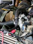
So basically the 24V and 14V leads are held in place by three clamps each, one on the thermostat housing, one on the front of the right head and one on a body flange, the pictures so how it is routed, the two leads are routed together, in some pictures the 14V lead is not apparent being hidden behind the 24V lead.
On the body flange I used a (will measure and edit) long 5/16 bolt/washers, I bolted the 24V lead in first from underneath the flange and secured it with a nut, then I secured the 14V lead with washers and a second nut, this means I did not have to fight both leads at the same time...
The AC mounting kit came with a bolt where the original stud held the original wire harness to the front of the right head (same as bottom seen in picture) but there was a long stud included with the 200A kit so I used it in place of the top AC bracket bolt, made that task much easier.
Also without the AC the leads would take a lower path between the front of the right head and the body flange, but because the compressor would interfere I "hung" them a little higher off of the heater hoses to clear the compressor.

A WORD HERE ABOUT TIE WRAPS,,,, These are really great!! but do yourself a big favor, if you do not have a tie wrap installation tool get yourself some "NIPPY CUTTERS" then you can cut the tie wrap off completely flush so you are not ripping your skin off later with the knife edge ends left when cutting them off with a standard set of diagonal cutters...
OK, now install the provided grommet in the existing battery box hole directly behind the shunt, route the wires through the grommet and connect the 24V lead to the large post in front of the shunt and the 14V wire to the battery terminals between the batteries.
Pay close attention to where the wires run and how they "lay" avoiding anything sharp or hot (as in exhaust hot)
The 200A alternator has a "soft start" feature so it will not start charging right away, it delays just long enough for panic to set in......
The red wire coiled up on top of the alternator is to carry 14V to the "accessories" and will be put in asphalt loom when run.1.jpg2.jpg4.jpg6.jpg7.jpg8.jpg9.jpg
The green wire in the battery box is for the 24V rear winch.
 
Last edited:

Retiredwarhorses

Well-known member
Steel Soldiers Supporter
4,254
3,839
113
Location
Brentwood, Calif
Couple things here.
The winch per the TM wires direct too the starter pos and neg.
The 14v tap runs too the rear battery positive to prevent imbalance on 4L80 equipped truck.
if your running a 3 speed truck, you can just abandon the 14v tap, or run it too the rear battery Positive and run all your
12v accessories from that rear battery only, do NOT use body grounds and don’t use the front battery to pull 12v.
it does appear that your gauge wire on the winch feed may be a bit small, I always use welding cable 4/0.
 

Mogman

Moderator
Staff member
Moderator
Steel Soldiers Supporter
5,872
8,184
113
Location
Papalote, TX
Couple things here.
The winch per the TM wires direct too the starter pos and neg.
The 14v tap runs too the rear battery positive to prevent imbalance on 4L80 equipped truck.
if your running a 3 speed truck, you can just abandon the 14v tap, or run it too the rear battery Positive and run all your
12v accessories from that rear battery only, do NOT use body grounds and don’t use the front battery to pull 12v.
it does appear that your gauge wire on the winch feed may be a bit small, I always use welding cable 4/0.
Yes it may be a little small but is still rated for about 200A for its length and meets the winch manufactures recommendation, (it is larger than was supplied with the winch BTW) And It is what I had, not every HMMWV owner can drop big bucks on 4/0 welding wire which is absurdly oversized, 2/0 is good to over 300A at up to 22 feet, I am happy you can give yourself so much "overhead"
There is no practical difference between the starter and the power terminals in the battery box except the starter is easier to damage and all the current going to the starter goes through the battery box terminal anyway, and it is just one more set of connections exposed to the elements.
I believe everyone installing a dual voltage alternator understands and wants to take advantage of being able to draw from the rear battery, so I did not think I needed to mention it, but thank you for pointing that out.
 

Retiredwarhorses

Well-known member
Steel Soldiers Supporter
4,254
3,839
113
Location
Brentwood, Calif
Yes it may be a little small but is still rated for about 200A for its length and meets the winch manufactures recommendation, (it is larger than was supplied with the winch BTW) And It is what I had, not every HMMWV owner can drop big bucks on 4/0 welding wire which is absurdly oversized, 2/0 is good to over 300A at up to 22 feet, I am happy you can give yourself so much "overhead"
There is no practical difference between the starter and the power terminals in the battery box except the starter is easier to damage and all the current going to the starter goes through the battery box terminal anyway, and it is just one more set of connections exposed to the elements.
I believe everyone installing a dual voltage alternator understands and wants to take advantage of being able to draw from the rear battery, so I did not think I needed to mention it, but thank you for pointing that out.
unless you haven’t done so, that’s why from the factory, the starter and battery pos are encased in RTV, to prevent said corrosion. And no...many folks upgrade to the 200amp because the 60amp is garbage, plus you must have a 100-200 to run A/C, so many folks never use the 14v tap. The other reason is, the 200 amp is the direct replacement for the 60 and are 1000 times more reliable than a 60amp. it’s easier to find a 200 now than a 60amp.
 

Ajax MD

Well-known member
1,571
1,420
113
Location
Mayo, MD
Couple things here.
The winch per the TM wires direct too the starter pos and neg.
The 14v tap runs too the rear battery positive to prevent imbalance on 4L80 equipped truck.
if your running a 3 speed truck, you can just abandon the 14v tap, or run it too the rear battery Positive and run all your
12v accessories from that rear battery only, do NOT use body grounds and don’t use the front battery to pull 12v.
it does appear that your gauge wire on the winch feed may be a bit small, I always use welding cable 4/0.
Aha! This explains my configuration. I have that alternator but the 14v wire was not run. I have the 3L80 transmission.
I would like to run that wire to power low, 12v loads like a cell phone charger.
 
Top
AdBlock Detected

We get it, advertisements are annoying!

Sure, ad-blocking software does a great job at blocking ads, but it also blocks useful features of our website like our supporting vendors. Their ads help keep Steel Soldiers going. Please consider disabling your ad blockers for the site. Thanks!

I've Disabled AdBlock
No Thanks