If you haven't done so already you need to test the circuit to see where it's broken.
Start it up and first verify you have 24V on the X terminal of K1
If so, follow the instructions in the TM, it will tell you to manually connect the Y terminal to ground with a jumper. If K1 is good it should close when you ground the Y terminal. If not, the K1 contactor is either bad or stuck.
If it does close, that indicates a failure somewhere in the ground path between K1-Y terminal and the S5 switch.
You can then work backwards from K1-Y to S5 and figure out where the ground gets lost.
If you do not have 24V on K1-X, run a jumper to any +24 source, such as the battery etc.
Retest the contactor using the switch as normal. If it works now, you need to back track through the oil pressure switch to see where your +24V signal got lost.
If you have power and ground at X and Y , don't take the mallet suggestion as a joke. I'm dead serious, it works quite often.
Hold S5 up and whack the top of K1 If it works, then you just need to determine why the contactor is sticking.
Also, Have you checked S5 yet, to make sure it's wired correctly and it's working?
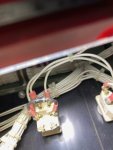
Did you put the markings on the connectors of K1 or has someone else been in there messing around before you ?


")