• Steel Soldiers now has a few new forums, read more about it at: New Munitions Forums!

  • Microsoft MSN, Live, Hotmail, Outlook email users may not be receiving emails. We are working to resolve this issue. Please add support@steelsoldiers.com to your trusted contacts.


Air Conditioning a Deuce

DHennon

Member
Steel Soldiers Supporter
364
16
18
Location
Orlando, Fl
I have seen a number of posts lately regarding members purchasing a/c kits for their Deuce. I bought my Deuce in October, 2010 and purchased a new a/c unit from AUTOCAR in California, and had him ship to me here in Florida. It was a brand new unit and sat in the crate until this past March. Since I received the unit, I have been reading all the posts I could find on the SS site for previous installs and there are not, unfortunately, many. Knowing what I have learned up to now, I can see why!
I want to first thank AUTOCAR for all the info he provided in answering questions and assisting with the shipping and loading in California. M-35tom sent me a template to fabricate the compressor bracket. Last, but certainly not least, a special thanks to Zout who was invaluable in answering installation questions, providing pictures and a wiring diagram from the manufacturer. I believe he was the pioneer in installing the first system in a M35. The local National Guard Motor Pool spent an afternoon showing me where this a/c system was mounted in their new 2 1/2 version of the M35A2.
Since the M35 was never designed to be air conditioned, there was a great deal of fabricating, trial and error fitting, and some Rube Goldberg engineering necessary for the installation.
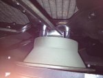
To date, I have the compressor installed, the condenser mounted on the front of the radiator, and the evaporator mounted (temporarily) in the cab, under the map compartment. I still need to connect the hoses, hook up the electrical, and charge the system.
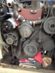
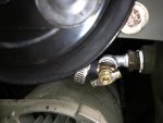
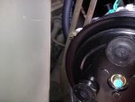
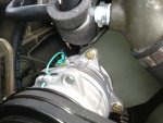
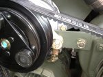
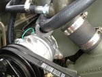
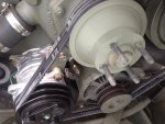
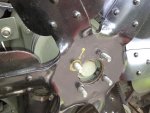
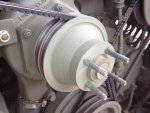
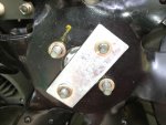
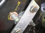
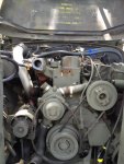
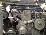
I first needed to mount the compressor somewhere on the front of the engine, easily accessible, and in line with the existing pulley set up.
I first disconnected the batteries, set the parking brake, and chocked the wheels. I drained the antifreeze in a clean bucket for reuse. I just flushed the cooling system, replaced the belts and hoses, replaced the thermostat, added new antifreeze, and installed a coolant filter.
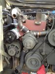
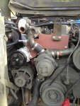
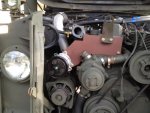
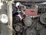
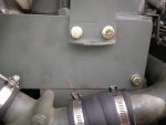
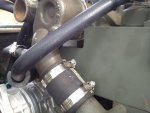
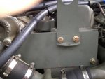
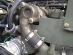
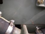
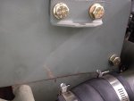
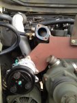
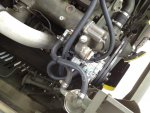
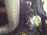
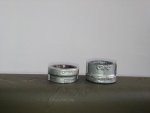
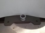
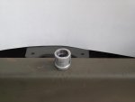
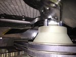
I removed the grill guard, radiator, and radiator/lifting ring from the front of the cylinder head.
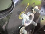
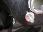
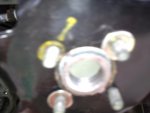
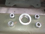
Next I removed all the coolant hoses, heater hose connections, and thermostat housing. Below are some pictures.


Attachments

Last edited:

3dAngus

Well-known member
4,719
101
63
Location
Perry, Ga.
Dave
You rock!
Keep em coming.
How is the newer compressor bracket working out?
Would you consider making another for me on consignment?
Keep us informed. Good stuff.
 

Autocar

Member
260
15
18
Location
California
Thank you for the kind words. I figured that I would never get around to installing the A/C in my M818, so I wanted someone to have it that could use it. I'm anxious to see how you mount everything in the cab.
 

HanksDeuce

Well-known member
1,079
234
63
Location
Prairieville, LA
Dave,

Thanks a bunch for starting this thread. You said you would! I too would be interested in the possibility of purchasing a compressor bracket from you. Between work and other things the truck may be put on the back burner once I take her home from Timntrucks' house.
 

zout

Well-known member
7,744
154
63
Location
Columbus Georgia
Thanks for the kind words. I did have lots of pics of the entire build to the 109's - something like 880 pics and over 45,000 posts on the builds. I had a moderator remove my thread per request. Plus wiping out the posts as well but I did not care.

The pics I saved of the ac system I installed into Dinger65's 109 was a challenge and I found it quite recreational to install it - I love a challenge.

I belive it took me around 45 days in my spare time from getting the kit he supplied to firing it and testing it - we went camping together after we got it done and the operational aspect of it all works flawlessly and he has to turn it on low to keep from nearly freezing in the cab.

Personally - there is no frickin way I would add something like this no matter how hot it got - its just another thing to break down - when it was built it had nearly everything I required - then customized the chit out of it to turn it into the unit I did.

Glad to see someone other than myself tackle this system and get it in for their own needs to keep cool - I can appreciate that - but I have no need for one.

Keep the pics coming
 

DHennon

Member
Steel Soldiers Supporter
364
16
18
Location
Orlando, Fl
Now that I have the front end of the engine accessible, it is time to mount the compressor. I removed the small, L-shaped bracket to mount the clevis for the radiator support and the lift ring form the front of the cylinder head. In the photo, you will see I numbered the bolt holes 1, 2, & 3. These are the holes used to mount the compressor bracket to the cylinder head.
I had the machine shop fabricate a 3/8” steel plate to mount to the front of the head. The plate rests on the lip of the block where the head and block meet. I had a notch cut in the upper left corner of the plate, looking at the front of the engine, to clear the thermostat housing. The right side of the plate is perpendicular to the right side of the cylinder head.
I laid a machinist square on the lip of the block and drew a vertical line on the head up through the center of each of the 3 bolt holes on the front of the head, 1, 2, & 3. I put the plate on the lip and transferred the vertical lines to the plate. Next I measured up from the lip of the block to the center of each hole, and transferred the measurements to the plate, marked the location of each of the 3 holes, and drilled them out with my drill press.
Using the plate, I clamped the plate to the back to mounting holes on the compressor, marked the location to drill the holes to mount the compressor to the plate. After drilling the holes, I bolted the compressor to the plate and bolted the plate to the head. Be sure to install the Radiator support bracket and lift ring to the head when you install the plate. (In the pictures, the radiator bracket is upside down). After the trial fit, I removed the plate and painted it. I used all grade 8 bolts, washers, lock washers, and nuts.
 

Attachments

DHennon

Member
Steel Soldiers Supporter
364
16
18
Location
Orlando, Fl
Now that I have the front end of the engine accessible, it is time to mount the compressor. I removed the small, L-shaped bracket to mount the clevis for the radiator support and the lift ring form the front of the cylinder head. In the photo, you will see I numbered the bolt holes 1, 2, & 3. These are the holes used to mount the compressor bracket to the cylinder head.
I had the machine shop fabricate a 3/8” steel plate to mount to the front of the head. The plate rests on the lip of the block where the head and block meet. I had a notch cut in the upper left corner of the plate, looking at the front of the engine, to clear the thermostat housing. The right side of the plate is perpendicular to the right side of the cylinder head.
I laid a machinist square on the lip of the block and drew a vertical line on the head up through the center of each of the 3 bolt holes on the front of the head, 1, 2, & 3. I put the plate on the lip and transferred the vertical lines to the plate. Next I measured up from the lip of the block to the center of each hole, and transferred the measurements to the plate, marked the location of each of the 3 holes, and drilled them out with my drill press.
Using the plate, I clamped the plate to the back 2 mounting holes on the compressor, marked the location to drill the holes to mount the compressor to the plate. After drilling the holes, I bolted the compressor to the plate and bolted the plate to the head. Be sure to install the Radiator support bracket and lift ring to the head when you install the plate. (In the pictures, the radiator bracket is upside down). After the trial fit, I removed the plate and painted it. I used all grade 8 bolts, washers, lock washers, and nuts.
 

Attachments

Last edited:

southbreeze

New member
20
0
1
Location
Vancleave, MS
Big D, thanks for the pix and posts on this subject. I'll be doing two of these in the upcoming months....Thanks to 3dAngus's super sweet a/c deals.

Man that galvi street ell looks dangerous hiding back in there. If I was you, I'd get a brass/bronze replacement before you get to far along and cover that little dude up. We've seen a ton of trouble with the el cheapo galvi fittings offshore and they'll perforate in a heart beat. the metal is poruous and basically junk.

You've got some really good stuff going on and would hate to see you get bit and boil your engine out on that.

Thanks again for the pix and postings,
Paul
 

3dAngus

Well-known member
4,719
101
63
Location
Perry, Ga.
Nice clean work Dave. I was wondering, is there an adjustment for the compressor for stretched belts or alignment. I can't see any from this side.
 

DHennon

Member
Steel Soldiers Supporter
364
16
18
Location
Orlando, Fl
In picture #8 above, I reversed the alternator tensioning bracket and attached it back on the top of the Alternator and the slotted end to the top outside bolt hole on the a/c compressor. I went to Autozone and bougt two belts, part # 15550.

I also have included a few more pictures of the compressor install.
 

Attachments

Last edited:

3dAngus

Well-known member
4,719
101
63
Location
Perry, Ga.
:oops:

OK, I'm old and slow, but I got it now. I like it. Good work Dave. You got talent.
Looking forward to more pictures and more problem solving.
 

DHennon

Member
Steel Soldiers Supporter
364
16
18
Location
Orlando, Fl
Notice the fan hub in this attached picture. When the compressor is installed, the fan would not clear the compressor clutch. I purposely painted the fan blade tips yellow to be sure they cleared after I spaced the fan out 1/2 ". This initially presented a number of challenges. I will address how I solved those issuesin the next post, and hopefully will save those of you doing this install a GREAT deal of time! :)
 

Attachments

DHennon

Member
Steel Soldiers Supporter
364
16
18
Location
Orlando, Fl
Southbreeze,

Thanks for the recommendation on the galvanized fitting. I will pick up a brass one tomorrow. I was concerned I might over-tighten the brass one and break it off, as it has to face in the direction in the post, but will see if I can make the brass work. :beer:
 

DHennon

Member
Steel Soldiers Supporter
364
16
18
Location
Orlando, Fl
After installing the a/c compressor, I began putting the front end of the truck back together. I quickly found the truck has decided although I was ready, it wasn’t. Herein is when the real challenges reared their collective ugly heads!
The fan would not clear the compressor clutch. I needed to move the fan out toward the radiator about ½” to adequately clear the clutch. The problem presented was there is nothing to center the opening in the center of the fan blade. Originally the fan blade centers on the water pump pulley and is then held in place with the four fan blade bolts. Moving the blade out ½” left nothing but the 4 bolts to hold it on the pulley. Although this allowed for clearance from the a/c clutch, I did not feel all that spinning steel being held on with just the 4 -5/16” bolts was acceptable or safe.
To correct this, I went back to Ace, (I now have enough nuts and bolts from there, I almost could open my own fastening store), and bought 4, 5/16” exhaust manifold studs and several 5/16” steel spacers of various lengths. The ½” ones turned out to be the best choice. I only used the studs for the engineering part of the fan blade positioning. It was much easier sliding the fan blade on and off the stubs, rather than to use 4 bolts every time I wanted to check for proper clearance.
To solve the centering the fan blade and give it support, I fabricated a spacer from a 1” galvanized pipe coupling. First I drilled out the inside of the coupling with a 1” Silver and Deming drill bit (This removed most of the threads). I cut 5/8” off the end of the coupling and used that as the spacer between the fan hub and inside of the of the fan blade. It fit perfectly and gives the blade some support as well. I removed the studs and installed the fan blade, spacers, and galvanized centering spacer using 5/16” grade 8 bolts and lock washers. To keep the galvanized spacer in place, I fabricated a 1/8” steel plate to cover the spacer and used 2 of the fan blade bolt holes (diagonally) to fasten it to the fan. It will not move or come ou,t and now I have adequate clearance for the compressor clutch and plenty of clearance in front of the fan blade to the radiator.
 

Attachments

Top
AdBlock Detected

We get it, advertisements are annoying!

Sure, ad-blocking software does a great job at blocking ads, but it also blocks useful features of our website like our supporting vendors. Their ads help keep Steel Soldiers going. Please consider disabling your ad blockers for the site. Thanks!

I've Disabled AdBlock
No Thanks