Hello all,
Thank you all for some great info. Trying to return the favor I thought I'd post something that may be of interest. I recently got a 803 with low hours and needed to load it for break in and did not want to use the house each run, as well as better control over the load. A load bank. At first I thought of building a load panel with a multitude of outlets. It could double as a load center at a jobsite or something. I have a little 3000w generator I've tested with a couple of space heaters. But this would take eight or so, and even if I had all that, I'd probably never set it up but once. I really need something a little more purpose built. Here's what I came up with.
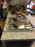
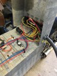
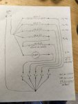
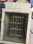
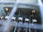
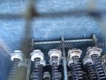
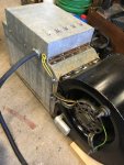
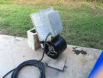
So, from my junk/parts shed (my wife calls it Mike's home depot) I sourced sheet metal, hardware cloth, some light U-channel (unknown origin), a 240v blower and two elements (each had two coils) from an old residential furnace, and a third element (single coil) that I think came from a large window unit that had a heat option. Using an ohm meter, I found the four furnace coils to be 14.6 ohms and the odd one to be 10.9 ohms. I calculated to put three of the 14.6 individually and series the fourth 14.6 with the 10.9 making 25.5 ohms total for that circuit. The fan I just powered up and took a amp reading. It ran about 2.5 amps. The three 14.6 ohm coils should be about 16.4 amps each and the 25.5 ohm combination should be about 9.4 amps. This combo seems to work well as I have managed to approximate 80%, 100%, and a little overload.
Putting this together.
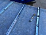
The air box dimensions were determined by the width of the fan and the length of the elements. All elements as used were supported on a wire frame. The furnace ones were the longest and had a single frame tip longer than the rest of the frame. I made the box depth where this tip would just fit through a hole on the back side for support. The stiffeners I added to the box double as physical protection of this frame tip extending from the box. The odd coil was not as long and had two frame tips for support. I used 1/4-20 bolts and rod couplings to extend "sockets" for this one to fit to. (loose bolt and rod coupling (long nut) shown in photo of the bottom).
Metal work.
I do not have a metal brake. Long bends were done by clamping the metal between two lengths of heavy angle iron that have sharp edges and then gently pushing and tapping with a hammer. As the bend progresses, you can get more aggressive with the hammer. Other bends were done with careful application of wide billed vise grips. Assembly was done with an assortment of pop-rivets and self tapping screws. The holes for the switches were laid out and carefully cut with a dremel tool.
Some important notes on the electrical.
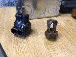
The switches were commercial grade rated at 277v and 20a. All circuits were tapped from the main feed. IE do not daisy chain the switches with smaller wire. Each circuit will carry its own current and therefore must be tapped from the feed individually. I chose to make one large joint. One photo shows a polaris block and a kerney. I used polaris blocks, but a kearney and judicious use of tape would suffice.
Also note that 120v rated coils may be used on 240v if the voltage drop is compatible. If for instance two 10 ohm coils in series would result in a 12a circuit at 240v, each coil would drop 120v, which would be acceptable. A 12 ohm and a 8 ohm coil would result the same, however the 12 ohm coil would drop 144v. It would need to be rated higher voltage. My point being mix and match, just make sure everything is rated for what you're doing. Do some research on "Ohms Law" if you don't know.
Of course any number of coils may be connected in series, just make sure voltage drop across each one is appropriate.
The main cable I used was 8/4 SO cord. The neutral was unnecessary as all loads were 240v, but it's what I had.
As far as actual, It worked great. I've so far run it 8hrs at 100% with no overheating of cables or the box.
Things I'd do different or change.
First off, I'd made the screen removable. It'll suck up leaves and then they're trapped.
Second, since the first, I'd make a disconnect for the fan, as it is now the only way to the inside.
A stand or dolly. Just large and heavy enough to be cumbersome.
All of these coils I left the thermal cutouts in place. It is the only protection. The only overcurrent is the 803's main. Since it will only be run supervised, I judged this ok.
So far, so good.
Hope this may be of use to somebody. Of course, I hold no liability for use of this info.
Best to all.
Thank you all for some great info. Trying to return the favor I thought I'd post something that may be of interest. I recently got a 803 with low hours and needed to load it for break in and did not want to use the house each run, as well as better control over the load. A load bank. At first I thought of building a load panel with a multitude of outlets. It could double as a load center at a jobsite or something. I have a little 3000w generator I've tested with a couple of space heaters. But this would take eight or so, and even if I had all that, I'd probably never set it up but once. I really need something a little more purpose built. Here's what I came up with.


So, from my junk/parts shed (my wife calls it Mike's home depot) I sourced sheet metal, hardware cloth, some light U-channel (unknown origin), a 240v blower and two elements (each had two coils) from an old residential furnace, and a third element (single coil) that I think came from a large window unit that had a heat option. Using an ohm meter, I found the four furnace coils to be 14.6 ohms and the odd one to be 10.9 ohms. I calculated to put three of the 14.6 individually and series the fourth 14.6 with the 10.9 making 25.5 ohms total for that circuit. The fan I just powered up and took a amp reading. It ran about 2.5 amps. The three 14.6 ohm coils should be about 16.4 amps each and the 25.5 ohm combination should be about 9.4 amps. This combo seems to work well as I have managed to approximate 80%, 100%, and a little overload.
Putting this together.
The air box dimensions were determined by the width of the fan and the length of the elements. All elements as used were supported on a wire frame. The furnace ones were the longest and had a single frame tip longer than the rest of the frame. I made the box depth where this tip would just fit through a hole on the back side for support. The stiffeners I added to the box double as physical protection of this frame tip extending from the box. The odd coil was not as long and had two frame tips for support. I used 1/4-20 bolts and rod couplings to extend "sockets" for this one to fit to. (loose bolt and rod coupling (long nut) shown in photo of the bottom).
Metal work.
I do not have a metal brake. Long bends were done by clamping the metal between two lengths of heavy angle iron that have sharp edges and then gently pushing and tapping with a hammer. As the bend progresses, you can get more aggressive with the hammer. Other bends were done with careful application of wide billed vise grips. Assembly was done with an assortment of pop-rivets and self tapping screws. The holes for the switches were laid out and carefully cut with a dremel tool.
Some important notes on the electrical.
The switches were commercial grade rated at 277v and 20a. All circuits were tapped from the main feed. IE do not daisy chain the switches with smaller wire. Each circuit will carry its own current and therefore must be tapped from the feed individually. I chose to make one large joint. One photo shows a polaris block and a kerney. I used polaris blocks, but a kearney and judicious use of tape would suffice.
Also note that 120v rated coils may be used on 240v if the voltage drop is compatible. If for instance two 10 ohm coils in series would result in a 12a circuit at 240v, each coil would drop 120v, which would be acceptable. A 12 ohm and a 8 ohm coil would result the same, however the 12 ohm coil would drop 144v. It would need to be rated higher voltage. My point being mix and match, just make sure everything is rated for what you're doing. Do some research on "Ohms Law" if you don't know.
Of course any number of coils may be connected in series, just make sure voltage drop across each one is appropriate.
The main cable I used was 8/4 SO cord. The neutral was unnecessary as all loads were 240v, but it's what I had.
As far as actual, It worked great. I've so far run it 8hrs at 100% with no overheating of cables or the box.
Things I'd do different or change.
First off, I'd made the screen removable. It'll suck up leaves and then they're trapped.
Second, since the first, I'd make a disconnect for the fan, as it is now the only way to the inside.
A stand or dolly. Just large and heavy enough to be cumbersome.
All of these coils I left the thermal cutouts in place. It is the only protection. The only overcurrent is the 803's main. Since it will only be run supervised, I judged this ok.
So far, so good.
Hope this may be of use to somebody. Of course, I hold no liability for use of this info.
Best to all.


