• Steel Soldiers now has a few new forums, read more about it at: New Munitions Forums!

  • Microsoft MSN, Live, Hotmail, Outlook email users may not be receiving emails. We are working to resolve this issue. Please add support@steelsoldiers.com to your trusted contacts.


Hydraulic Conversion of PTO Winch

mudguppy

New member
1,587
15
0
Location
duncan, sc
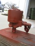
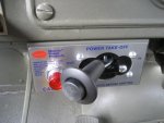
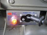
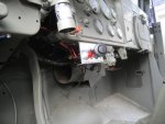
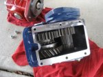
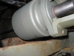
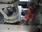
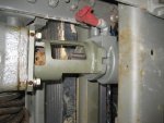
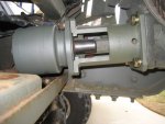
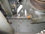
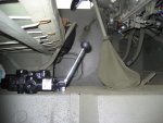
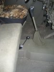
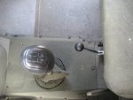
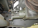
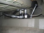
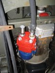
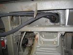
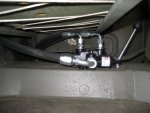
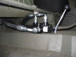
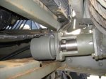
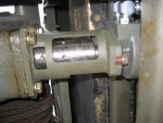
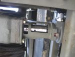
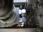
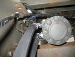
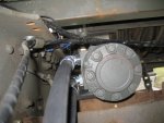
In my repower thread and disc brake thread, I mentioned a "Phase 2" of converting the PTO winch to hydraulic. Well, here it is.

Don't get too excited yet - it isn't quite complete. One fitting (yes, one) is on back-order. Can you believe it?

Anyway, I have taken a lot of pics, so let me share.

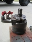
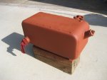
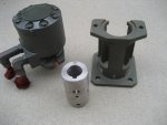
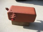
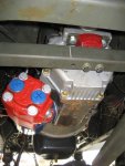
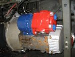
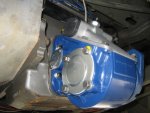
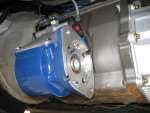
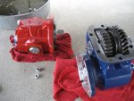
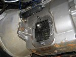
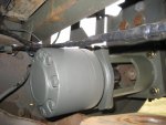
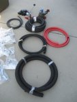
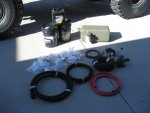
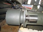
First up was to acquire the hard parts. From Justin Wehring I was able to source some A3 parts: hydraulic motor, motor stand, shaft coupler, and resevoir w/ filter mount.
 

Attachments

Keith_J

Well-known member
3,657
1,313
113
Location
Schertz TX
Nice. Using it stand-alone or driven off the power steering system? That would set directional control valve center spool type.

You can also eschew the shear pin nonsense by using a pressure relief valve set to limit bare drum maximum pull.
 

mudguppy

New member
1,587
15
0
Location
duncan, sc
PTO Mounting

Next up, I needed a PTO-mounted hydraulic pump and respective PTO adaptor for the NV4500 transmission.

Sizing the pump to the motor needed to be done carefully. I used a PTO calculator spreadsheet that was made by a company that speciallizes in doing such hydraulic conversions. I had to do some research on finding the specs of the A3 motor that I had acquired.

However, I needed to have a performance target. From various threads discussing winch performance and the research performed by Gringletaube I was able to define the OE PTO winch performance characteristics as the goal (operating RPM / line speed and actual line pull). With this info, I was able to define desired motor speed to maintain 25 fpm line speed (minimum, bottom layer) and system pressure to for 10,000 lbs line pull (top layer).

I ended up using a Muncie hydraulic pump (PKS15-02BPBB) and air-shift PTO adapter (PG6S-N7918-A1SH). Mounting this looked to be a bit sketchy because it did not look as though it would fit right. However, as promised it fit like a glove. I did end up clocking the pump 30° so that the rear In/Out fittings would clear the trans crossmember, but this was super-easy with the clocking ring designed into the adapter.
 

Attachments

mudguppy

New member
1,587
15
0
Location
duncan, sc
Nice. Using it stand-alone or driven off the power steering system? That would set directional control valve center spool type.

You can also eschew the shear pin nonsense by using a pressure relief valve set to limit bare drum maximum pull.
just hang on...
 

mudguppy

New member
1,587
15
0
Location
duncan, sc
Control Valve & Test Fit

Finding a convenient spot for a control valve in the cab of the deuce isn't easy. Essentially, there is only room for it in one spot. Before anyone asks, yes I could have gone with electronic solenoid control and operated off of toggle switches. I didn't want this.

I used a Prince valve RD512EA5A4B1 - this is a free-wheeling motor spool valve. Setting this under the bench next to the transfer shifter was the next best place and still quite within comfortable reach.

I also did a test fit of the motor, mount, and shaft coupler so I could get appropriate fittings on order.
 

Attachments

mudguppy

New member
1,587
15
0
Location
duncan, sc
Plumbing

Once I got everything laid out and distances estimated, I put a butt-load of hydraulic fittings and enough hose on order. Two weeks later, stuff is here. In the mean time, I also figured out the resevoir location, made a mounting system, cut out holes for hoses in/out of the cab and bed, and picked up some oil.

As it turns out, the tank from an A3 measures out to just over 9.5 gallons. Now, although this tank would not normally contain this much, I ended up buying 12 gal of hydraulic oil.

Earlier this week I got a call from the hydraulic place - the tank suction fitting thatneed is on back-order. The tank uses large ORB fittings which aren't easy to find locally on weekends.

Nonetheless, there was still plenty to do, so I plumbed what I could today; basically everything but the tank lines.
 

Attachments

Keith_J

Well-known member
3,657
1,313
113
Location
Schertz TX
Fancy install but you know you could have used your existing power steering pump to power the hydraulic motor for the winch.
 

mudguppy

New member
1,587
15
0
Location
duncan, sc
Winch Motor Fit

I was also able to do a final install of the hydraulic motor. The shaft coupler was initially looking like it was going to be a bear - it isn't an OE piece. Rather, it is a duplicated part. It is nice that it is machined out of stainless, but during mockup I realized that the fit was quite tight. I don't know how tight the OE coupler is. It turned out to not be a problem - I set it in the oven and it slid right on being 400°F and cooled to a nice shrink fit.

You will note that a shear pin is installed in the coupler; there is a reason. The PTO calculations showed that the pressure needed to achieve maximum line pull turned out to be 2012 psi. The control valve came set at 2000 psi. Nice coincidence!

Theoretically, the system should max out and relief pressure at just about the OE PTO setup. However, I'd feel more comfortable doing initial testing w/ an OE shear pin in there. Therefore, I plan to leave the pin in during testing - if the winch stalls before the shear pin fails (and the winch doesn't explode), then I should be able to replace the shear pin with a solid piece and not have to worry about either damaging the winch or losing pulling power due to fatigued pins.
 

Attachments

mudguppy

New member
1,587
15
0
Location
duncan, sc
So that's where I'm at until that silly fitting shows up. Soon as it does, I should be able to throw on the suction / return lines, fill 'er up, and test 'er out. That is, as long as I got the In / Out on the pump correct...

Stay tuned.
 

mudguppy

New member
1,587
15
0
Location
duncan, sc
Fancy install but you know you could have used your existing power steering pump to power the hydraulic motor for the winch.
yep, sure could have.

except I didn't want the winch to be 30% of line speed, <70% of the line pull, and neuter the power steering while in use.
 

gringeltaube

Staff Member
Super Moderator
Moderator
Steel Soldiers Supporter
6,879
2,252
113
Location
Montevideo/Uruguay
Very nice, clean build - as usual, Travis!

Just an idea for next time...: placing the control valve in the left-rear corner of the cab (this picture) would give you the option of also reaching the handle while standing outside and better watching/controlling the action.

Not clear: how would the shear pin still be the "fuse" link if the coupler now fits tight on the winch shaft?
Also, can that coupler still slide on the motor side, to compensate some (minimal) axial movement, from both shafts? i.e., OEM common ball bearing (!)wormshaft bearings taking excessive play... (Hyd. motors usually don't like high axial loads).

G.
 
Last edited:

Sephirothq

Well-known member
1,423
25
48
Location
Trevorton / PA
I also noticed that the hydraulic tank is not shown yet. It looks like another line still has to be installed from the valve to the tank and from the tank to the pump. Are you going to run a filter in the system?

It looks good so far. very interested in how it works.
 

sierra117

Member
188
1
18
Location
Isanti, MN
I was always wondering if a pto winch could be converted to hydraulic as the A3 I have uses a hydraulic setup. I am excited to see how it works out.
 

joshuaz223

New member
141
2
0
Location
Central Square, N.Y.
I also noticed that the hydraulic tank is not shown yet. It looks like another line still has to be installed from the valve to the tank and from the tank to the pump. Are you going to run a filter in the system?

It looks good so far. very interested in how it works.
The filter attachment can be seen in most of the tank pics. in the last pic a filter is on the tank fitting.

Guppy, great job as usual. love your truck and work so far.
 

mudguppy

New member
1,587
15
0
Location
duncan, sc
Very nice, clean build - as usual, Travis!

Just an idea for next time...: placing the control valve in the left-rear corner of the cab http://www.steelsoldiers.com/attach...ble_from_drivers_side_or_standing_outside.jpg would give you the option of also reaching the handle while standing outside and better watching/controlling the action. ...
G', that's actually exactly where I wanted to put it!!! However, I plan on adding a rear-mounted winch in the future. A dual-spool valve flat won't fit. The single spool valve won't fit w/ JIC fittings on the In/Out ports; however, I think it may fit if i use NPT fittings... maybe. I weighed the options and chose to reserve this area for the rear winch spool valve.

good to know that others think that is a good idea as well...


... Not clear: how would the shear pin still be the "fuse" link if the coupler now fits tight on the winch shaft? ...
Sorry, I may not have been clear before - the tight fit was on the motor shaft, not the winch input shaft. It fits the winch shaft well; snug, but still able to spin by hand, so it should utilize the shear pin w/out resistance.


... Also, can that coupler still slide on the motor side, to compensate some (minimal) axial movement, from both shafts? i.e., OEM common ball bearing (!)wormshaft bearings taking excessive play... (Hyd. motors usually don't like high axial loads). ...
Not really very much. I did think about this when I was test fitting. Final fitment was pretty snug. I actually left the motor mount loose on the winch, aligned and tightened the motor onto the mount, and let the shaft coupler do the final aligning. I gave it a couple complete rotations to let everything settle in before tightening the mount onto the winch. I really don't know if this helped, but is the best installation method I could think of to obtain decent alignment. We'll see how I did...
 

mudguppy

New member
1,587
15
0
Location
duncan, sc
I also noticed that the hydraulic tank is not shown yet. It looks like another line still has to be installed from the valve to the tank and from the tank to the pump. Are you going to run a filter in the system? ...
Yeah, the tank is going in the bed. Since I don't have the suction fitting, I cannot complete the circuit. I didn't want the tank sitting in the bed open outside, so it is still in the garage avoiding accumulation of condensation.

Good eye - no tank means that the return line from the valve is not there yet either. The outlet port on the valve and inlet on the pump are both capped until I can get the tank in.

Yes, there is a filter on the return port of the tank. I just picked up a new filter yesterday.
 

mudguppy

New member
1,587
15
0
Location
duncan, sc
Did you use the stock (M35a2) winch mounting brackets and the frame extensions? How did the length turn out on the front end?
Yes, the winch mounting is all OE - all originally installed on the truck. No modifications were done to the winch whatsoever. It's been there the whole time.

The mount and motor fit nice and snug above the front crossmember - it was made to go there.... literally.
 

mudguppy

New member
1,587
15
0
Location
duncan, sc
Top
AdBlock Detected

We get it, advertisements are annoying!

Sure, ad-blocking software does a great job at blocking ads, but it also blocks useful features of our website like our supporting vendors. Their ads help keep Steel Soldiers going. Please consider disabling your ad blockers for the site. Thanks!

I've Disabled AdBlock
No Thanks