


- 1,350
- 886
- 113
- Location
- State College, PA
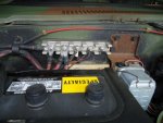
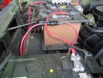
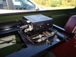
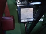
Having just installed a new HF radio and accessories on the rear radio rack in the M1009, I wanted to convert the existing 24 volt bus bar to 12 volts. And I wanted to have a better location to access 12 volts other than the one near the glow plug relay. It is limited for high current demands and relies on the stock wiring.
The rear bus bar would need to provide a good source of power for 20-40 amps of current draw and I wanted it to be on it's own fuse. Should the radio or any accessories develop a problem (short), the vehicle wiring would not be compromised.
Here is a description of how I accomplished this with out much trouble and minimal modifications to the vehicle wiring.
1. Disconnect the batteries.
2. Remove all the nuts from the positive bus bar studs on the firewall.
3. Remove the wires from the studs.
4. Remove the metal bus bar from the studs.
5. Install a suitable insulating material on one edge of the bus bar about 1 inch from the edge. I used heat shrink tubing but a few wraps of electrical tape would work. This was done for piece of mind knowing that a live electrical conductor is not exposed to accidental shorting.
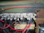
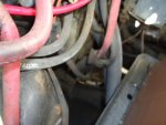
6. Reinstall the bus bar one hole off to the left so the insulated portion is toward the passenger fender and the stud next to the fuel filter has nothing attached to it.
7. Reattach all the wires to the bus bar with the exception of the factory installed wire that is run to the rear bus bar.
8. Connect the wire to the rear bus bar to the stud that is next to the fuel filter.
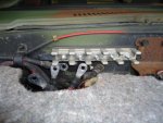
9. Install a new wire from the stud that has the rear wire attached to the positive terminal of the front battery. Be sure to install a fuse as close as possible to the battery. I used an AGU style fuse holder and #2 stranded wire.
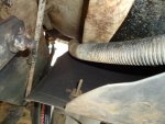
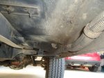
10. Secure the wires and fuse holder.
11. Reconnect batteries.
This modification is easily accomplished and is easily reversible should you want to convert the rear bus bar back to 24 volts.
It's also a good idea to clean all electrical connections before reassembly.
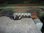
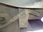
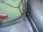
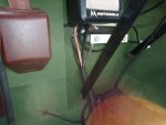
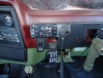
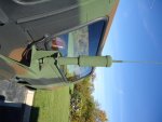
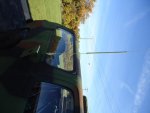
Attached are a few pictures of my installation.
Karl
The rear bus bar would need to provide a good source of power for 20-40 amps of current draw and I wanted it to be on it's own fuse. Should the radio or any accessories develop a problem (short), the vehicle wiring would not be compromised.
Here is a description of how I accomplished this with out much trouble and minimal modifications to the vehicle wiring.
1. Disconnect the batteries.
2. Remove all the nuts from the positive bus bar studs on the firewall.
3. Remove the wires from the studs.
4. Remove the metal bus bar from the studs.
5. Install a suitable insulating material on one edge of the bus bar about 1 inch from the edge. I used heat shrink tubing but a few wraps of electrical tape would work. This was done for piece of mind knowing that a live electrical conductor is not exposed to accidental shorting.
6. Reinstall the bus bar one hole off to the left so the insulated portion is toward the passenger fender and the stud next to the fuel filter has nothing attached to it.
7. Reattach all the wires to the bus bar with the exception of the factory installed wire that is run to the rear bus bar.
8. Connect the wire to the rear bus bar to the stud that is next to the fuel filter.
9. Install a new wire from the stud that has the rear wire attached to the positive terminal of the front battery. Be sure to install a fuse as close as possible to the battery. I used an AGU style fuse holder and #2 stranded wire.
10. Secure the wires and fuse holder.
11. Reconnect batteries.
This modification is easily accomplished and is easily reversible should you want to convert the rear bus bar back to 24 volts.
It's also a good idea to clean all electrical connections before reassembly.
Attached are a few pictures of my installation.
Karl
Attachments
-
 41.7 KB Views: 286
 -
 44.3 KB Views: 265
 -
 44.9 KB Views: 262
 -
 52.3 KB Views: 265
 -
 52.6 KB Views: 264

 or
or 