


SpaceGhost
New member
- 9
- 15
- 3
- Location
- Idaho
Hi all,
I purchased a M1078 A1 in October of last year. I drove her from Western Washington to Northern Idaho on the Montana boarder with no issues. During the winter, I started her every two weeks and got up to operating temperature (to the point the fan turned on). A few weeks ago, when I went to move the truck for the first time since parking for the winter, I fell victim to the dreaded "no start" issue. Actually, it started up fine, but then once it came up to temperature, I noticed "Check Trans" was illuminated and the transmission control panel was not illuminated. Not knowing the significance of this, I figured I would just restart the truck, but as many of you know (and I have come to find out) if the "Check Trans" is illuminated, power is cut off to the ignition switch.
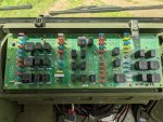
I used the troubleshooting guide on Transmission Instrument's website and thought I diagnosed the problem to the WTEC III ECU, so I sent them the WTEC III and control panel to to diagnose/fix; however, both checked out fine. John with Transmission Instruments noted that the error code indicated that the WTEC III lost power while the engine was running. He recommended that I clean any oxidation in the power lines starting with the battery box. I cleaned all the terminals and connections in both the battery box and the main cutoff switch area, but still have the "Check Trans" light on. I rechecked the WTEC III again, and test lam would still dimly light up when checking the battery ground and power on the grey connector (pins #17, #32 and #16, #17, respectively). I rechecked the ignition power (grey connector #17 to black connector #4) and got a bright light. However when I rechecked the battery ground and power on the grey connector, the test light did not illuminate... It seems like it's a break in the wire somewhere. I check the back of the power distribution panel (PDP) and found no loose connections. I currently have no voltage at the CB79 fuse, and I'm not sure what my next step should be.
Incidentally, the LD2 and LD3 lights on my PDP are illuminated. I tried looking up the significance of this, but could not find anything. I included an image of my PDP because I realize there are a few different ones out there.
Hopefully this makes sense and someone can point me towards what I should be checking next.
Thank you!
I purchased a M1078 A1 in October of last year. I drove her from Western Washington to Northern Idaho on the Montana boarder with no issues. During the winter, I started her every two weeks and got up to operating temperature (to the point the fan turned on). A few weeks ago, when I went to move the truck for the first time since parking for the winter, I fell victim to the dreaded "no start" issue. Actually, it started up fine, but then once it came up to temperature, I noticed "Check Trans" was illuminated and the transmission control panel was not illuminated. Not knowing the significance of this, I figured I would just restart the truck, but as many of you know (and I have come to find out) if the "Check Trans" is illuminated, power is cut off to the ignition switch.
I used the troubleshooting guide on Transmission Instrument's website and thought I diagnosed the problem to the WTEC III ECU, so I sent them the WTEC III and control panel to to diagnose/fix; however, both checked out fine. John with Transmission Instruments noted that the error code indicated that the WTEC III lost power while the engine was running. He recommended that I clean any oxidation in the power lines starting with the battery box. I cleaned all the terminals and connections in both the battery box and the main cutoff switch area, but still have the "Check Trans" light on. I rechecked the WTEC III again, and test lam would still dimly light up when checking the battery ground and power on the grey connector (pins #17, #32 and #16, #17, respectively). I rechecked the ignition power (grey connector #17 to black connector #4) and got a bright light. However when I rechecked the battery ground and power on the grey connector, the test light did not illuminate... It seems like it's a break in the wire somewhere. I check the back of the power distribution panel (PDP) and found no loose connections. I currently have no voltage at the CB79 fuse, and I'm not sure what my next step should be.
Incidentally, the LD2 and LD3 lights on my PDP are illuminated. I tried looking up the significance of this, but could not find anything. I included an image of my PDP because I realize there are a few different ones out there.
Hopefully this makes sense and someone can point me towards what I should be checking next.
Thank you!
Attachments
-
 169.4 KB Views: 21
")