


Jerds19
New member
- 23
- 16
- 3
- Location
- Austin/Texas
Hello all, having a starting issue and I can't figure out why my Cranking Relay (K2) isn't getting any power when trying to operate from the front panel switch (S1).
X2 has ground no matter what position S1 is in.
X1, A1 and A2 never receiver power, regardless of S1 position (prime/run or start).
Fuel solenoid (L5) never receives power or actuates regardless of S1 position.
When setting S1 to prime/run the fuel pump actuates and gauges work, relays inside actuate assumingly correctly as some of them tick.
When setting S1 to start, there is an audible clunk coming from the starting solenoid (L4), and voltage drops from 24ish down to 20ish, but there is no cranking attempted.
When use the dead crank switch (S10) the cranking relay does get power to X1, A1 and A2, the generator will crank but will not start because fuel solenoid never receives power/actuates. If I manually retract fuel solenoid and crank from S10 it will start and run, produce AC power and work fine until I release start solenoid and then it shuts off.
So I know the batteries, starter, starter solenoid work.
I have gone through the -20 per advice from users on this forum and everything tests out fine up until step 18, "test for defective cranking relay". The tests don't however tell you WHICH wires are suppose to be powered coming into the K2, but since NONE of them are getting power there is obviously an issue. (Going past 18 to 19 and 20, I have confirmed 19 start solenoid works, and 20 starting motor works).
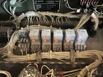
Assuming the device prior to the cranking relay in the electrical circuit would be one or two of the relays... S14? K12? K16? maybe all of them working in unison?
One of my concerns is that on S14, there are no wires connected to the A or B (activation) terminals, so there is no way to actually actuate the relay. This might be normal as they do call this a "switch" not a "relay". But it is entirely possible that there are missing wires on this unit, which will likely make it a nightmare.
Can anyone help me understand which pins are suppose to be powered on these relays when the generator is in the "run" position? I'm looking at the F0-1 Schematic, and I see the flow charts, but can't find anything that shows pinouts. All the troubleshooting tells me is how to confirm the relay is WORKING, and all the relays appear to be perfectly functional, but that doesn't confirm that all the wires into the relay sockets are wired properly (or there). It appears to me that for some reason, there is probably one wire that suppose to be hot that powers the start relay and the fuel solenoid that isn't going hot, and I can't figure out why.
There are no diagnostic lights showing errors, and again it will start and run from dead crank switch with fuel solenoid held open, so that tells me that there is enough things connected properly for it to crank and run from dead crank, just not from S1. So I feel like there is some "check" or "sensor" that is telling the system it isn't ready to run, but I can't figure out what. I have been told, which may be incorrect, that if the unit is low on oil or fuel the unit won't crank and run. However the "engine fails to crank" flowchart on page 54 never even mentions those things.
Any advice would be appreciated!
X2 has ground no matter what position S1 is in.
X1, A1 and A2 never receiver power, regardless of S1 position (prime/run or start).
Fuel solenoid (L5) never receives power or actuates regardless of S1 position.
When setting S1 to prime/run the fuel pump actuates and gauges work, relays inside actuate assumingly correctly as some of them tick.
When setting S1 to start, there is an audible clunk coming from the starting solenoid (L4), and voltage drops from 24ish down to 20ish, but there is no cranking attempted.
When use the dead crank switch (S10) the cranking relay does get power to X1, A1 and A2, the generator will crank but will not start because fuel solenoid never receives power/actuates. If I manually retract fuel solenoid and crank from S10 it will start and run, produce AC power and work fine until I release start solenoid and then it shuts off.
So I know the batteries, starter, starter solenoid work.
I have gone through the -20 per advice from users on this forum and everything tests out fine up until step 18, "test for defective cranking relay". The tests don't however tell you WHICH wires are suppose to be powered coming into the K2, but since NONE of them are getting power there is obviously an issue. (Going past 18 to 19 and 20, I have confirmed 19 start solenoid works, and 20 starting motor works).
Assuming the device prior to the cranking relay in the electrical circuit would be one or two of the relays... S14? K12? K16? maybe all of them working in unison?
One of my concerns is that on S14, there are no wires connected to the A or B (activation) terminals, so there is no way to actually actuate the relay. This might be normal as they do call this a "switch" not a "relay". But it is entirely possible that there are missing wires on this unit, which will likely make it a nightmare.
Can anyone help me understand which pins are suppose to be powered on these relays when the generator is in the "run" position? I'm looking at the F0-1 Schematic, and I see the flow charts, but can't find anything that shows pinouts. All the troubleshooting tells me is how to confirm the relay is WORKING, and all the relays appear to be perfectly functional, but that doesn't confirm that all the wires into the relay sockets are wired properly (or there). It appears to me that for some reason, there is probably one wire that suppose to be hot that powers the start relay and the fuel solenoid that isn't going hot, and I can't figure out why.
There are no diagnostic lights showing errors, and again it will start and run from dead crank switch with fuel solenoid held open, so that tells me that there is enough things connected properly for it to crank and run from dead crank, just not from S1. So I feel like there is some "check" or "sensor" that is telling the system it isn't ready to run, but I can't figure out what. I have been told, which may be incorrect, that if the unit is low on oil or fuel the unit won't crank and run. However the "engine fails to crank" flowchart on page 54 never even mentions those things.
Any advice would be appreciated!
Last edited:


")
