- 1,962
- 3,054
- 113
- Location
- Pepperell, Massachusetts
MEP-831A SLC100 Governor Controller
Having purchased a couple of MEP-831A's I found that the SLC100 Governor Controllers are problem prone. The two Tier 2 Reset units I purchased with just 2 hrs on the clock both randomly exhibited surging issues as well as random WOT issues. Adjustment of the SLC100 Governor Controllers was futile.
I dropped about $350 on a new SLC100 from GCA to repair one of my 831A's and knew there had to be a better solution than dropping more than 50% of a 831 purchase price on a new controller!
Being a retired DOD engineer and not not being satisfied with the analog, moisture prone design issue of the SLC100 I decided to design a replacement for the SLC100 governor controller for the 831A. After studying the TM, the tuning procedure and the operation of the SLC100 I came up with a design that eliminates the primitive analog feedback system employed in the SLC100 with the four moisture prone potentiometers.
Operational description:
The SLC100 takes two inputs to determine the appropriate setting of the engines throttle actuator. The first is the frequency from the PMA (engine RPM) and the second is the %Load applied signal from the inverter. The SLC100 operates to adjust the voltage to the actuator so that the engine RPM is approximately proportional to the applied load. To operate correctly the SLC100 must be operating properly as well as having the GAIN, BOOST, RPM and STABILITY potentiometers set correctly. Sometimes a PITA to adjust correctly.
The prototype unit employs two circuits that convert the PMA frequency output which is proportional to the engine RPM as well as the inverters %Load output. The PMA's frequency is converted to a digital frequency using a opto-isolator. The opto-isolator's digital frequency output is fed to a Frequency to Voltage convertor who's output is sent to a 8 bit microcomputer to measure the engine RPM. More on the 8 bit RISC microcomputer later.
The invertors Load sensing output is also sent to the 8 bit microcomputer. It's a 0-5 VDC level representing 0-%100 load.
Based on the PMA "Frequency" input and the %Load input the microcomputer then adjusts the 831's actuator to achieve the appropriate engine RPM based on the load applied. Adjustment of the actuator position is achieved using a PWM (Pulse Width Modulated) output from the microcomputer to trigger a NPN darlington transistor to control the actuators position by varying the "voltage" to it.
The microcomputer constantly monitors the PMA frequency (engine RPM) and %load to constantly maintain the correct engine RPM.
The 8 bit RISC (Reduced Instruction Set Computer) microcomputer is a ATTINY85.
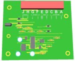
Here is a picture of the prototype replacement. The 14 pin IC is the Frequency to Voltage convertor, the 8 pin IC is the 8 bit ATTINY85 RISC microcomputer, the 4 pin IC is the opto-isolator. Device headers contain the needed resistors and diodes to make the PMA Frequency sensor and %Load sensor circuits work. The TO-220 device is the darlington power transistor to control the 831A's actuator position. The big green resistor is part of the PMA opto-isolator Frequency conversion circuit. The two TO-92 devices are +5 and +12 VDC voltage regulators to power the various prototype circuits.

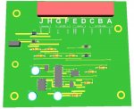
Close up of prototype. Not pretty, hey it's a prototype!

A picture of the prototype installed in one of my 831A's

Here is a video of one of the initial runs today of the prototype installed in one of my 831A's. The video is of the initialization, lifting the actuator target off the magnet (not shown), initial start, adjustment to no load RPM, application of 1.5 KW load with throttle up, application of 3 KW load with more throttle up to full load RPM, reduction of load to 1.5 KW with throttle down, reduction of load to 0 KW with return to idle RPM and then final shutdown. All controlled with the prototype governor controller.
https://www.youtube.com/watch?v=UeFscHrwO1c
After more testing my hope is to turn the design into a proper PWB design and possibly make units available for sale. Target is to potentially make the replacement available for much less than a new SLC100. PWB design underway already.
The big bonus is no need to tune the 4 potentiometers and eliminate the moisture issue. "Production" controllers would be 100% conformally coated.
Wish me luck!
Having purchased a couple of MEP-831A's I found that the SLC100 Governor Controllers are problem prone. The two Tier 2 Reset units I purchased with just 2 hrs on the clock both randomly exhibited surging issues as well as random WOT issues. Adjustment of the SLC100 Governor Controllers was futile.
I dropped about $350 on a new SLC100 from GCA to repair one of my 831A's and knew there had to be a better solution than dropping more than 50% of a 831 purchase price on a new controller!
Being a retired DOD engineer and not not being satisfied with the analog, moisture prone design issue of the SLC100 I decided to design a replacement for the SLC100 governor controller for the 831A. After studying the TM, the tuning procedure and the operation of the SLC100 I came up with a design that eliminates the primitive analog feedback system employed in the SLC100 with the four moisture prone potentiometers.
Operational description:
The SLC100 takes two inputs to determine the appropriate setting of the engines throttle actuator. The first is the frequency from the PMA (engine RPM) and the second is the %Load applied signal from the inverter. The SLC100 operates to adjust the voltage to the actuator so that the engine RPM is approximately proportional to the applied load. To operate correctly the SLC100 must be operating properly as well as having the GAIN, BOOST, RPM and STABILITY potentiometers set correctly. Sometimes a PITA to adjust correctly.
The prototype unit employs two circuits that convert the PMA frequency output which is proportional to the engine RPM as well as the inverters %Load output. The PMA's frequency is converted to a digital frequency using a opto-isolator. The opto-isolator's digital frequency output is fed to a Frequency to Voltage convertor who's output is sent to a 8 bit microcomputer to measure the engine RPM. More on the 8 bit RISC microcomputer later.
The invertors Load sensing output is also sent to the 8 bit microcomputer. It's a 0-5 VDC level representing 0-%100 load.
Based on the PMA "Frequency" input and the %Load input the microcomputer then adjusts the 831's actuator to achieve the appropriate engine RPM based on the load applied. Adjustment of the actuator position is achieved using a PWM (Pulse Width Modulated) output from the microcomputer to trigger a NPN darlington transistor to control the actuators position by varying the "voltage" to it.
The microcomputer constantly monitors the PMA frequency (engine RPM) and %load to constantly maintain the correct engine RPM.
The 8 bit RISC (Reduced Instruction Set Computer) microcomputer is a ATTINY85.
Here is a picture of the prototype replacement. The 14 pin IC is the Frequency to Voltage convertor, the 8 pin IC is the 8 bit ATTINY85 RISC microcomputer, the 4 pin IC is the opto-isolator. Device headers contain the needed resistors and diodes to make the PMA Frequency sensor and %Load sensor circuits work. The TO-220 device is the darlington power transistor to control the 831A's actuator position. The big green resistor is part of the PMA opto-isolator Frequency conversion circuit. The two TO-92 devices are +5 and +12 VDC voltage regulators to power the various prototype circuits.
Close up of prototype. Not pretty, hey it's a prototype!
A picture of the prototype installed in one of my 831A's
Here is a video of one of the initial runs today of the prototype installed in one of my 831A's. The video is of the initialization, lifting the actuator target off the magnet (not shown), initial start, adjustment to no load RPM, application of 1.5 KW load with throttle up, application of 3 KW load with more throttle up to full load RPM, reduction of load to 1.5 KW with throttle down, reduction of load to 0 KW with return to idle RPM and then final shutdown. All controlled with the prototype governor controller.
https://www.youtube.com/watch?v=UeFscHrwO1c
After more testing my hope is to turn the design into a proper PWB design and possibly make units available for sale. Target is to potentially make the replacement available for much less than a new SLC100. PWB design underway already.
The big bonus is no need to tune the 4 potentiometers and eliminate the moisture issue. "Production" controllers would be 100% conformally coated.
Wish me luck!
Last edited: