• Steel Soldiers now has a few new forums, read more about it at: New Munitions Forums!

  • Microsoft MSN, Live, Hotmail, Outlook email users may not be receiving emails. We are working to resolve this issue. Please add support@steelsoldiers.com to your trusted contacts.


Putting together a 80mph speedo kit.

Mattguy

Well-known member
Steel Soldiers Supporter
755
1,329
93
Location
Highland, Indiana
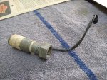
I've slowly got almost all the pieces for a 80mph electronic speedo conversion. Have everything except transfer case electronic sender and what looks like a diode board. Has anyone installed the kit? And is the diode board necessary? I can't even find a PDF of the installation instructions from the kit and all the tm's just show parts numbers and diagrams. The kit number is 57K4882.
 
  • Like
Reactions: OBX

springer1981

Well-known member
844
1,148
93
Location
Maine
Not sure what a diode board is, the drawing doesn't show it. There is a resister board but that doesn't seem to be a part of the wiring but maybe to relocate the heater resister for clearance issues? Do you have a cannon connector on the back of the speedometer or a terminal strip?

wiring.jpg
 

Mattguy

Well-known member
Steel Soldiers Supporter
755
1,329
93
Location
Highland, Indiana
Not sure what a diode board is, the drawing doesn't show it. There is a resister board but that doesn't seem to be a part of the wiring but maybe to relocate the heater resister for clearance issues? Do you have a cannon connector on the back of the speedometer or a terminal strip?

View attachment 893186
Its number 10. That must be for the heater and it is a resistor board like you said. Weird that it's part of the speedo kit. Now just to find the backordered #7 speedo sender unit. I'm also trying to figure out where the 2 y taps go. I know one is for power, and i assume the other is for the backlight.
 

springer1981

Well-known member
844
1,148
93
Location
Maine
Its number 10. That must be for the heater and it is a resistor board like you said. Weird that it's part of the speedo kit. Now just to find the backordered #7 speedo sender unit. I'm also trying to figure out where the 2 y taps go. I know one is for power, and i assume the other is for the backlight.
#10 is the resister relocate board.
 

Mattguy

Well-known member
Steel Soldiers Supporter
755
1,329
93
Location
Highland, Indiana
Thank you @86humv! Got my sender today and hopefully I'll try to install this weekend. Still looking for instructions for installation can't figure out the under dash wiring part.

Repeat buyer from 86humv. Great guy.
 
Last edited:

badgerd

Electronic Jedi
102
63
28
Location
Chesapeake VA
Here’s some notes I made after doing mine (and my own built harness). Cable numbers and locations are correct, I’m still looking for the “official” instructions as well but it works just fine!View attachment Electronic Speedo Install notes.pdf


You do need splitters, and not normal ones, to get power and light to the gauge. They’re shown in the manual pic on the last page. Easy to make, so I’ve never looked for them.
 
Last edited:

Mattguy

Well-known member
Steel Soldiers Supporter
755
1,329
93
Location
Highland, Indiana
Here’s some notes I made after doing mine (and my own built harness). Cable numbers and locations are correct, I’m still looking for the “official” instructions as well but it works just fine!View attachment 894024


You do need splitters, and not normal ones, to get power and light to the gauge. They’re shown in the manual pic on the last page. Easy to make, so I’ve never looked for them.
Thank you! I have the harness, 2 splitters, sender and speedo. Along with the clips and screws in the TM . This will help me out!!
 

Mattguy

Well-known member
Steel Soldiers Supporter
755
1,329
93
Location
Highland, Indiana
Here’s some notes I made after doing mine (and my own built harness). Cable numbers and locations are correct, I’m still looking for the “official” instructions as well but it works just fine!View attachment 894024


You do need splitters, and not normal ones, to get power and light to the gauge. They’re shown in the manual pic on the last page. Easy to make, so I’ve never looked for them.
Did you run the harness thru the place where the speedo cable is at? I didn't see the picture where you put the harness thru.
 

badgerd

Electronic Jedi
102
63
28
Location
Chesapeake VA
Did you run the harness thru the place where the speedo cable is at? I didn't see the picture where you put the harness thru.
Yup! I removed the grommet from the old cable by cutting a slice in it and put it on the new harness. I followed the speedo cable for install and grounded to the transfer case by changing the ground lug to a slightly larger size and using a bolt on it.

When I put that together it was raining so I didn’t take pics of the harness install. Maybe someday I’ll update it.


Sent from my iPhone using Tapatalk
 
Top
AdBlock Detected

We get it, advertisements are annoying!

Sure, ad-blocking software does a great job at blocking ads, but it also blocks useful features of our website like our supporting vendors. Their ads help keep Steel Soldiers going. Please consider disabling your ad blockers for the site. Thanks!

I've Disabled AdBlock
No Thanks