2INSANE
Well-known member
- 722
- 819
- 93
- Location
- Belgrade, Montana
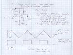
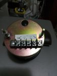
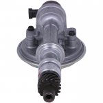
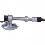
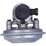
I was searching the web and found a few images of a 6.2 diesel vacuum pump with a tach speed sensor.
Is this a part that can be ordered or is it custom modified?
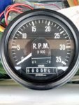
My goal is too hook up my tachometer to a better signal but yet still keep the vacuum pump in the same location.
Is this a part that can be ordered or is it custom modified?
My goal is too hook up my tachometer to a better signal but yet still keep the vacuum pump in the same location.
Attachments
-
 36.5 KB Views: 22
 -
 22.6 KB Views: 22
 -
 58.2 KB Views: 25
 -
 65.7 KB Views: 22