• Steel Soldiers now has a few new forums, read more about it at: New Munitions Forums!

  • Microsoft MSN, Live, Hotmail, Outlook email users may not be receiving emails. We are working to resolve this issue. Please add support@steelsoldiers.com to your trusted contacts.

M1078A1 "Pandora" Build | 2024-??? | ***Picture Heavy***

Ronmar

Well-known member
3,350
6,748
113
Location
Port angeles wa
I would remove that female QC from the wet tank drain. They are not meant to be out in the weather and will corrode quickly. They also tend to fill up and jam with road grime. Mine gave me nothing but problems, even when I slid a rubber boot over it. i would instead put in a ball valve and a male QC fitting.

A female QC there kind of defeats the purpose of being able to purge moisture from what is supposed to be a filter/separator stage in the system.
A male QC and a ball valve still serve this purpose as well as allowing you to charge or use air from the system. You just need a female-female adapter or female-female hose for the truck that you can keep stored out of the weather when not needed to use air from the truck…

Yours being an A0, I suspect the wet tank is not plumbed into the system correctly anyway. The Wet tank is supposed to act as a secondary cooler/dryer and settling tank so the brakes get the cleanest driest air. In order to serve in this capacity, 100% of the air must pass THRU the wet tank.

Well some bright light at S&S got it wrong, and since the diagrams in the manuals were probably created from the prototypes, they show it wrong in all the manuals that show tank service as well. The only place it is shown correctly is on page 34 of the schematics. Instead of running the air THRU the wet tank, they “T“d the wet tank off the dryer output line to the service tanks. Plumbed like this, i would say less than 1/5 of the brake air ever sees the inside of the wet tank.

Simple mistake, and lucky for us very easy to fix, you simply swap two of the line connections and their end fittings on the wet tank using the hardware thats already there.

Every A1 truck I have looked at is plumbed correctly with 100% of the brake air passing THRU the wet tank…

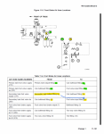
Here is how it looks from the factory and in the tank service diagrams in the manual.
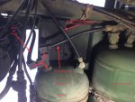

IMG_2650.jpeg


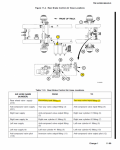
Here is how it should look, with 100% of the air forced thru the wet tank to get to the brake service tanks.

IMG_2663.jpeg
 
Last edited:

InvictusDecretum

Active member
61
137
33
Location
NC
I would remove that female QC from the wet tank drain. They are not meant to be out in the weather and will corrode quickly. They also tend to fill up and jam with road grime. Mine gave me nothing but problems, even when I slid a rubber boot over it. i would instead put in a ball valve and a male QC fitting.

A female QC there kind of defeats the purpose of being able to purge moisture from what is supposed to be a filter/separator stage in the system.
A male QC and a ball valve still serve this purpose as well as allowing you to charge or use air from the system. You just need a female-female adapter or female-female hose for the truck that you can keep stored out of the weather when not needed to use air from the truck…

Yours being an A0, I suspect the wet tank is not plumbed into the system correctly anyway. The Wet tank is supposed to act as a secondary cooler/dryer and settling tank so the brakes get the cleanest driest air. In order to serve in this capacity, 100% of the air must pass THRU the wet tank.

Well some bright light at S&S got it wrong, and since the diagrams in the manuals were probably created from the prototypes, they show it wrong in all the manuals that show tank service as well. The only place it is shown correctly is on page 34 of the schematics. Instead of running the air THRU the wet tank, they “T“d the wet tank off the dryer output line to the service tanks. Plumbed like this, i would say less than 1/5 of the brake air ever sees the inside of the wet tank. Simple mistake, and lucky for us very easy to fix, you simply swap two of the line connections on the wet tank using the hardware thats already there. Every A1 truck I have looked at is plumbed correctly…

Here is how it looks from the factory and in the tank service diagrams in the manual.


View attachment 924243


Here is how it should look, with 100% of the air forced thru the wet tank to get to the brake service tanks.


View attachment 924244
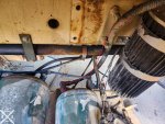
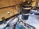
Thank you for bringing this to my attention ! I just went outside and checked. Despite mine being an early "A1" mine is plumbed differently than the A0. It has the air dryer/unloader going in to the front port, and the rear port to the service tanks (along with another thin line I did not trace)

20240525_141816 export edit.jpg

20240525_141903 export.jpg

FWIW that female QC is only on there to charge the truck with air from my garage compressor while I work on it. When I service the air brakes and replace all the 20yo air lines, I have the original drain valve to put back on there along with a Purest air dryer. I want to plumb in a female QC or two somewhere protected but will also put a ball shutoff valve before it/them after your warning. I've never had an issue with these Milton ColorFit Coupler & Plug Kit - Red-1/4" NPT, 14-Piece but I put a generic brass one on the wet tank since it wasn't permanent. This one has lived on that ARB manifold in my 2.8L Duramax Colorado for 5yrs or so without issue, but it is in the engine bay.


20210910_150634.jpg

This is my first air brake truck, and watching a YouTube couple almost get stranded in their unimog w/ air over hydraulic... I came to the following realizations:

  1. When you have an air leak on a straight hydraulic brake truck's On Board Air (OBA) you can't fill up tires/river floats as fast-if at all.
  2. When you have an air leak on an airbrake truck... You're a word that is prohibited on these forums but can be any part of speech.

@Ronmar any idea why the tanks are supposed to be drained in that order ? middle, front, rear/wet ? Batt box lid says "Drain tanks in sequence"

20240524_162440 export.jpg
 
Last edited:

Ronmar

Well-known member
3,350
6,748
113
Location
Port angeles wa
Cool, thats how it is supposed to be, all dryer air passing thru the wet tank. Like I said, I havn't seen an A1 plumbed incorrectly yet:) I think whoever was assembling them realized their error and just started assembling them correctly at some point, but didn’t bother announcing their error which would have forced them going back to fix all the previous trucks, and alter the manuals(a relatively big deal)… I have seen no tech bulletins published indicating this ever happened.

It’s not a horrendously big deal if your dryer is working properly, and not being overworked by excessive leakage. But it would help contain a dryer failure to the wet tank. i have a friend who missed service on and had a purest dryer cartridge fail/rupture internally and deliver filter media downstream.

If you have a 3126 and a circuit board power panel, but no battery disconnects or LBCD, I call those an A0.5…

aux systems that use air:
ctis. Supplied from the wet tank protection valve(large line).
fan control(and mid axle power divider lock). Typically tapped off ctis air in the cab.
cab suspension, small line split off from the ctis line just after the wet tank protection valve, runs over to the hydraulic manifold valve block
air for air op hydraulic pump. Comes from a remote control valve Td off of the service brake tanks, over to the hydraulic manifold valve block. The remote control valve disables the AOP supply whenever park air is applied(releasing park brakes).

I wonder what that little line is on the wet tank output to the service tanks? I am not aware of any other systems that use air…

i did a video on removing the AOP remote control supply valve from the service tanks as I did away with the AOP system entirely. I wonder whats on the inboard end of your service tanks, and if they drew AOP air from there. Thats not a lot of air. Two full service tanks can lift the cab twice. One full wet tank might struggle lifting the cab one time…

Here is a link to the AOP control valve delete…


InvictusDecretum

Active member
61
137
33
Location
NC
Cool, thats how it is supposed to be, all dryer air passing thru the wet tank. Like I said, I havn't seen an A1 plumbed incorrectly yet:) I think whoever was assembling them realized their error and just started assembling them correctly at some point, but didn’t bother announcing their error which would have forced them going back to fix all the previous trucks, and alter the manuals(a relatively big deal)… I have seen no tech bulletins published indicating this ever happened.

It’s not a horrendously big deal if your dryer is working properly, and not being overworked by excessive leakage. But it would help contain a dryer failure to the wet tank. i have a friend who missed service on and had a purest dryer cartridge fail/rupture internally and deliver filter media downstream.

If you have a 3126 and a circuit board power panel, but no battery disconnects or LBCD, I call those an A0.5…

aux systems that use air:
ctis. Supplied from the wet tank protection valve(large line).
fan control(and mid axle power divider lock). Typically tapped off ctis air in the cab.
cab suspension, small line split off from the ctis line just after the wet tank protection valve, runs over to the hydraulic manifold valve block
air for air op hydraulic pump. Comes from a remote control valve Td off of the service brake tanks, over to the hydraulic manifold valve block. The remote control valve disables the AOP supply whenever park air is applied(releasing park brakes).

I wonder what that little line is on the wet tank output to the service tanks? I am not aware of any other systems that use air…

i did a video on removing the AOP remote control supply valve from the service tanks as I did away with the AOP system entirely. I wonder whats on the inboard end of your service tanks, and if they drew AOP air from there. Thats not a lot of air. Two full service tanks can lift the cab twice. One full wet tank might struggle lifting the cab one time…

Here is a link to the AOP control valve delete…

My A0.5 does not have that Air Over Pump remote valve on the forward service tank, so maybe that line is the little one that comes off the wet output ?

Appreciate your posts here, here, and this video.

My forward tank looks similar to the end of your video, except it looks like my service tanks do not share air between each other. Those are one way valves on the input, correct ? Could the "A1" trucks only share air at the front and rear of the truck via checkvalves, off either tank ? That way if there is damage to either tank, it wouldn't depressurize both ?

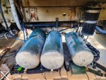
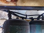
On the forward service tank, the center is plugged and the other port is T'd off and the lines run to the front and rear of the truck.

The middle tank has two outputs, one large line running to the rear and one "regular" size line running to the rear & front.

20240525_153532 export.jpg


The "regular line" off the forward service tank running front and rear connects here in the rear:
1716667721900.png

Large line to the rear off center service tank connects here:
1716667804264.png

It's 90* outside, 100% humidity, and there is a swarm of mosquitoes out so I didn't follow the lines any further, but I absolutely will in the future to decode the A0.5 air system...
 
Last edited:

InvictusDecretum

Active member
61
137
33
Location
NC
Seems like the tanks are only tied together at the front and rear of the truck; there is no tank to tank transfer on the A0.5/A1. As best I can tell the front brake hose routing is the same on the A0 and A1... but wont find out for sure until I pull the bed... which is after battery box mod, then ecohubs, then cab stripping for heat/sound insulation + airconditioning + seats + carpet + kitchen sink.

I'll definitely make a visio diagram of what I find similar to the electrical diagrams I've been making. Mostly for my reference, but maybe someone else will benefit as well.

Thank you for all your time so far teaching me how to fish !

1716670490128.png

1716670358940.png
 

Ronmar

Well-known member
3,350
6,748
113
Location
Port angeles wa
If you don’t have the remote valve, I suspect that line on the wet tank output is indeed for the AOP supply.

The primary and secondary/rear and front systems are separated(required by Fed motor vehicle safety standards, FMVSS). Those one way checks on their inlet are supposed to keep them that way. You test this by filling the system till the dryer purges, then shutting down. Drain the primary tank. The secondary gauge should stay where it was. Then refill and repeat the process except drain the other tank. The other full tank should remain at pressure.

the lines running forward from each tank are each Td into and feed a 2way check-valve under the dash. That combined 2way output supplies park and trailer control air. This is also where the pri and sec gauge sensors sample their air. The other port on the T fittings connects to the pri and sec inputs to the pedal. The pedal is two mechanical pressure regulators in a common housing. The 2way check valve is supposed to allow the outputs of 2 separate systems to feed a single system without interacting/cross-feeding.

The secondary output of the pedal feeds right down to a QR valve behind the bumper and on to the front actuators., so pedal air feeds the front brake actuators directly.

Primary pedal output goes all the way back to the weight proportioner and the relay Valve.

The two smaller lines from the pri and sec tanks running aft are used for comparison and to feed the trailer controls. The larger primary line feeds the supply for the brake relay. Since the rear uses 4 larger cans, feeding all that air thru the pedal would creat a lot of lag. So they only really send a pressure signal from the pedal to the relay, adjusted/proportioned according to the weight in the bed, to activate the control the relay.

The relay in-turn is a remote pressure regulator. Whatever pressure it sees on its input, it copies on its output, using air from its supply port to supply(and drain) the rear brake cans rapidly. These different pathways serve to keep the brake response similar between front and rear axles, with the fronts probably slightly lagging behind the rears when applied, but releasing slightly faster than the rears when the pedal is lifted.

i did a video for a friend going over how the rear components operate.

 
Top