• Steel Soldiers now has a few new forums, read more about it at: New Munitions Forums!

  • Microsoft MSN, Live, Hotmail, Outlook email users may not be receiving emails. We are working to resolve this issue. Please add support@steelsoldiers.com to your trusted contacts.

Looking for V100 chassis pics

Paweł

Active member
47
137
33
Location
Poland
@Buck Wampum - thank you so much for these photos! The coolest thing of all is they come exactly on time - on many occasions I got good reference after it was too late...
And these photos just show how bad the Hobby Boss chassis really is...
One thing that confirms the feature from the drawing I posted is that the shaft tunnel is not exactly straight, but a little diagonal, so to say.
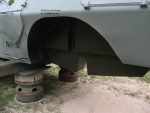
Another surprise for me is the shape of the underside below the engine - I thought the hull bottom there is flat with a cutout for the axle, and your photos show that it's V-shaped with the axle at the point of the V.
I'll see if I can incorporate those features in my model! Thanks again and have a nice day
Paweł
 

Buck Wampum

Active member
Steel Soldiers Supporter
64
131
33
Location
SE PA
@Buck Wampum - thank you so much for these photos! The coolest thing of all is they come exactly on time - on many occasions I got good reference after it was too late...
And these photos just show how bad the Hobby Boss chassis really is...
One thing that confirms the feature from the drawing I posted is that the shaft tunnel is not exactly straight, but a little diagonal, so to say.
Another surprise for me is the shape of the underside below the engine - I thought the hull bottom there is flat with a cutout for the axle, and your photos show that it's V-shaped with the axle at the point of the V.
I'll see if I can incorporate those features in my model! Thanks again and have a nice day
Paweł
The floor of the engine department is flat. The axle has a tunnel in the floor that it runs through. She attached pictures.
 

Attachments

Paweł

Active member
47
137
33
Location
Poland
Hello Scott!
Thanks a lot for more photos - they are very interesting!
What I wrote about previously is a comment to this photo you posted:
1707129747333.png
I expected the lower edge, where the cutout for the rear axle is to be straight, but it's V-shaped. And that fact is hidden in most photos, where the spring is installed. Now I'm thinking about how to modify my model to incorporate this feature.

Thanks again for your great help and have a nice day

Paweł
 

Rooper90

New member
6
11
3
Location
Liberec Czech Republic
Hello Pawel!


I'm glad I'm not the only modeller who ignores the completely wrong bottom of the hull of the V-100 by Hobby Boss.
With the help of local experts thanks to their photos, I've so far made an idea of how I'll make it out of plastic plates. I'll personally do the whole bottom part again, I won't use anything from the original bottom of the Hobby Boss.

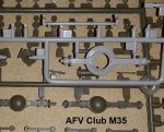
As for the axles, I'm considering using 5ton axles from the AFV Club M54A2 kit. They're very nicely processed including hubs and brake drums. Of course they'll want to be modified but as a default muster they're very adequate. I've also looked at the axles from the AFV Club M35 2.5ton kit, but there they seem quite undersized.

However, what is depicted as axles in the kit is absolutely insane!!
The envelopes of the internal differentials are absurdly large and the envelopes of the differentials themselves are strange boxes that absolutely do not correspond with reality!

George K.
 

Paweł

Active member
47
137
33
Location
Poland
Hello George!
Let's see, maybe we can work together on this one? I'm also doing some of my modelling in 3d and 3d printing parts, but this underside is tricky with all these angled surfaces, so I'm trying to mock everything up in styrene first and make sure it fits the upper shell, which is quite OK, especially compared to the underside...
As for the axles they say that the original V-100 or M706 had the 2,5 ton axles which were upgraded to 5 ton axles in V-150 and later machines. It is also said that Hobby Boss patterned parts of their model after a V-150, that's why the axles in the kit are so funny.
I personally don't think the AFV Club axles are undersize - they might seem that way compared to what's in the M706 kit, but I think they are OK. Compared to AFV Clubs 5 ton axles they look OK, so I think I'll draw up a pair of 2,5 ton axles and 3D print them. This way I can also show the front wheels turned - I mean posed as for turning.
Good luck with your 3D drawings and have a nice day
Paweł
 

Rooper90

New member
6
11
3
Location
Liberec Czech Republic
Hi Pawel
It also occurred to me to draw 2.5ton axles in a 3D program and then print them. Unfortunately, I'm not so skilled in 3D modeling and my brother, who is an engineer who models products for the automotive industry, still doesn't have time :D
I would certainly welcome cooperation, there is a saying in the Czech Republic "more heads - more knows"
Unfortunately, I don't have any free time to model anything these days. Hopefully it will be better by the end of February and I will be able to sit down and create something.

George K.
 

M813rc

Well-known member
Steel Soldiers Supporter
4,200
3,176
113
Location
Near Austin, Texas
Fortunately, having the real vehicles and several kits on hand, I can compare them all to each other. :)

Having looked at the axles in my AFV Club M35 kit, they look the correct size for the V100, and a few details would make them proper.
The axles in the M54 kit are too big (as they should be on a 5-ton), but could be used for a V150.
The ones that come with the kit are big enough for a 10-ton!

Your interior diagram is basically accurate, I have made some notes on it. As mentioned before, there are a lot of detail pictures in my restoration thread linked above.

Cheers

Interior b.jpg 20240205_110556 - Copy.jpg 20240205_110716 - Copy.jpg 20240205_110945 - Copy.jpg 20240205_111004 - Copy.jpg
 

Paweł

Active member
47
137
33
Location
Poland
Hello Rory!
Your restoration thread is so cool - I admire your dedication and skill, and the pictures you took are a great reference.
As for the kit axles - If I sanded off those absurd collars, they could very well pass for five ton axles, but that's still incorrect. I don't know how that part is called, where the driveshaft goes in, or rather through, but that's incorrect, too, no offset to the side, no sign of U-joints. I just have to make new ones!
Thanks a lot for your help and have a nice day
Paweł
 

Paweł

Active member
47
137
33
Location
Poland
Hello Rory!
Since you're asking, I'd gladly post some photos. But I'm just starting this one, you know...
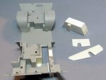
Here are two to remind what we have to work with:

1707262303472.jpeg

Now I started to cut it apart. I have built new rear fenders out of styrene sheet, and am generally trying to do the rear first:
1707262438962.jpeg

1707262651753.jpeg
I'm trying to prepare this one to have an accurate radioman's station and pose the hatches open. I want to convert the left rear only on the out side and leave the inaccuracies unseen on the inside of the engine bay.
Thanks for looking and have a nice day
Paweł
 

Attachments

Paweł

Active member
47
137
33
Location
Poland
Hello!
I started working on a 3D model of a 2,5 Ton axle:

1707692689087.png

This way I can 3D print them and won't have to rob my Deuse-and-a-half kit.

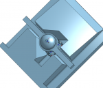
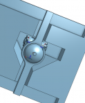
I can also "virtually" check for fit and design the axle tunnel on my model:

1707693033309.png

As you can see the axle tunnel still needs reworking.

Thanks for looking and have a nice day!
Paweł
 
Last edited:

Paweł

Active member
47
137
33
Location
Poland
Hello!
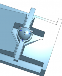
I feel like I'm on the right track now... I started working on the front tunnel:

1708817397168.png

And here is how it would work together with the front axle:

1708817497672.png

Does it look OK?

Thanks for looking and have a nice day

Paweł
 

Paweł

Active member
47
137
33
Location
Poland
Hello!
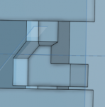
Small update - I drew up the transmission cover, since I felt it was necessary:

1709161029239.png

I plan to use the parts I have for the top portion of the engine compartment. This is also to keep the dimensions of the 3D print down.

Thanks for looking and have a nice day

Paweł
 

Paweł

Active member
47
137
33
Location
Poland
Hello!

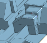
I have some progress here:

1709953173348.png

I think I'm going to the printers with it to ask how much this is going to cost. I think I'll 3D print one, try to fit it to the Hobby Boss Body, maybe make some adjustments and then print another one. I still have to finish my axles, too.

Thanks for looking and have a nice day

Paweł
 

Paweł

Active member
47
137
33
Location
Poland
Thanks a lot for your comment and for your kind words, Rory! I couldn't really make it if it weren't for this forum and your pictures!
Thanks again and have a nice day
Paweł
 

Paweł

Active member
47
137
33
Location
Poland
Hello everybody!
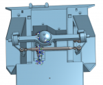
I'd say I'm done with the axles. Here's what it looks like:
1711580907436.png

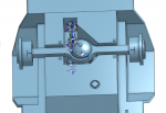
And rear looks like this:
1711580969117.png

I want to have a hole through both axles to be able to reinforce them with a steel wire. I want the wheels to be able to rotate and I want the front wheels to be positionable - a model looks better with the wheels turned slightly to side. I plan to print the axles together with the drive shafts. If you have any suggestions I would love to hear them, but please don't wait, because I would love to have something printed as soon as I have some money to pay for it :)
Thanks for looking and have a nice day

Paweł
 
Top
AdBlock Detected

We get it, advertisements are annoying!

Sure, ad-blocking software does a great job at blocking ads, but it also blocks useful features of our website like our supporting vendors. Their ads help keep Steel Soldiers going. Please consider disabling your ad blockers for the site. Thanks!

I've Disabled AdBlock
No Thanks