• Steel Soldiers now has a few new forums, read more about it at: New Munitions Forums!

  • Microsoft MSN, Live, Hotmail, Outlook email users may not be receiving emails. We are working to resolve this issue. Please add support@steelsoldiers.com to your trusted contacts.


Civilizing the MEP-002A

Craig A Tull

New member
94
0
0
Location
Papalote TX
I saw a thread some time ago asking what folks had done to “civilize” the MEP-002A
I have always considered the MEP as an over engineered piece of equipment.
Well the latest MEP-002A I bought is going to my sisters ranch in the hill country and she will never need the capability to switch phase, etc. so I am going to try and “simplify” it somewhat.
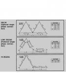
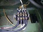
I am going to leave the motor controls as is, it seems simple enough, but I am going to rip out EVERYTHING on the generator side, hard wire the 12 wire generator output for 240V three wire single phase, install two matching 50 amp meters and current transformers to monitor L1 and L2, a single 250 volt meter that can be switched to read L1-L0 L2-L0 or L1-L2 and a simple 4 wire regulator, probably a Flight Systems 480.

Now I must insert a warning to anyone messing with current transformers on these generators THEY CAN FORCE YOUR BODY TO ASSUME ROOM TEMPERATURE!!

These transformers have a turns ratio of at least hundreds and some thousands to one and are meant to always have a shunt (short) applied to them, the switch on these generators are the “make before break” type and shunt (short) any current transformers that are not connected to the meter which is a low impedance “shunt” type meter. If the secondary of these transformers are open (not shorted) for any reason they will produce many thousands of volts and can fry your butt in a most awesome and spectacular way!!!

Craig
 

Craig A Tull

New member
94
0
0
Location
Papalote TX
Because it is designed to be powered bu CVT1 and the A4 board and as I said all that will be gone, it is not necessary in the single output role, the "universal" regulator just uses residual output from the generator output to power the field coil and is really cheap (under $200) and it also has only 4 wires so even my 65 year old sister could afford to have a spare and be able to swap it out. The regulator and A4 board are over 30 years old and as with any electronics are prone to failure.
If you look at the schematic everything to the left of S1 but the generator head itself will be gone only having the new meters and regulator described above, hertz meter is not necessary if nobody screws with the knob which I will probably remove, I have had many civilian Onan generators and have never seen one that could be adjusted or needed to be adjusted without tools.
 

Isaac-1

Well-known member
1,970
48
48
Location
SW, Louisiana
I agree in concept with what your doing, and Flight Systems does certainly make some good equipment I am just not sure if you will see a reliability improvement going that route over the stock voltage regulation systems assuming it is in good shape given your are trading Tantalum capacitors on the original board for probably Electrolytic capacitors on the Flight Systems board, etc. I might say go ahead and change out the output transistor on the stock board, since they are a common point of failure and perhaps check the CVT for insulation break down, but other than being a bit esoteric the stock voltage regulation on a whole seems fairly reliable. Either way it does not sound like your sister will be repairing a failed voltage regulator if one should fail.
 

Craig A Tull

New member
94
0
0
Location
Papalote TX
She will not have to, she will have a calibrated spare and only 4 wires to change, in fact I might even put a molex plug on it for her, also P9 is totally fried on this machine and what ever caused it not withstanding I don't like changing those plugs and the phase switch looks to have some questionable work done on it and might be the cause of aforementioned P9 being fried (prettiest blue flames you have ever seen) . AND I have always wanted to rip all that CRA% out of there because it just is not necessary AND I will have better metering, I don't think you can meter both voltage and current on both L1 and L2 individually the way it is now.
I have a DJA more or less half of that MEP and have owned it for 33 years and it was old when I got it, yes it has brushes and it uses the gen for a starter just like my little Lister LR-1 3kw, after modified to 4 brushes on the slip rings I have not had one issue with them in all these years and that little DJA has a crap load of hours on it, and I don't think ether has any semiconductors on them at all, the CVT and that regulator that can be used in a pot load of different generators are just not necessary.
And yes of course what ever fails on this will be something I did not see coming, but it won't be from old electronics or fuel lines, I am doing a complete spin on upgrade and replacing all the fuel lines also.
Craig
 
Last edited:

dependable

Well-known member
1,720
187
63
Location
Tisbury, Massachusetts
If I can't figure how to link back, maybe someone else can , (or you could have spent a short time finding the thread you mentioned) Started on 7/14/12. Maybe check it out before you start one like it so we all have it on the same thread.

Isaac-1 in above post #4 started it.

Save us all a lot of typing.
 
Last edited:

Craig A Tull

New member
94
0
0
Location
Papalote TX
Actually Isaac you have a point, if this machine was in working condition I would not even consider this radical modification, If it works don't screw with it! But as I said there are some disturbing problems, add to that My desire to do this modification and the perfect storm appears on the horizon, I have handled several of these for myself and friends, and of course I will have some spare parts left over for my machines.
 
Last edited:

Craig A Tull

New member
94
0
0
Location
Papalote TX
Also Isaac I had to cringe when you mentioned Tantalum capacitors, I am also a radio tech and a Ham and restore and operate allot of Harris equipment and the Tantalum capacitor is by FAR the least dependable component in any radio and if I were king they would be outlawed as they don't just fail they catch on FIRE!!!
 

Triple Jim

Well-known member
1,373
277
83
Location
North Carolina
In the 002A and 003A regulators, the tantalum capacitors are current limited by resistors in all cases except the big 150 uF one from pin 12 to pin 14. Even that one's current is limited by what T1 can supply, so I don't think failure by thermal runaway is really a concern in this case.
 

Craig A Tull

New member
94
0
0
Location
Papalote TX
Has anyone removed the reconnect switch and hard wired one for single phase? I have found the "standard" reconnect wiring diagrams for Onan generators and that looks straight forward but trying to compare that with the TM 5-6115-584-34 Table 6-5 "reconnection switch continuity" is a nightmare and Table 6-5 seems to have a boatload of errors
 

Craig A Tull

New member
94
0
0
Location
Papalote TX
Here is an example of single phase connections, note this is NOT the MEP diagram although I am sure it would also work fine, there are many different ways to get to the same point!!
 

Attachments

Last edited:

Craig A Tull

New member
94
0
0
Location
Papalote TX
OK I just found table 2-4 in TM9-6115-584-24P, the MEP uses the double delta as above, so we are off to the races, although I may use the "preferred" ZIG ZAG
 
Last edited:

Craig A Tull

New member
94
0
0
Location
Papalote TX
Well here is my idea for replacing the entire distribution box, that is a 60 amp "shorting" barrier strip from Ideal, originally it had a shorting bar in the center between the lugs and two or more brass bolts could be screwed in to short any 2-3 or all 4 of the positions, I thought it would be an "ideal" place to pick up voltage for the instrumentation and regulation so I removed the shorting bar, the two delta connections (I used the double delta scheme) that were not connected to anything else were simply spiced, soldered, sealed and buried in the harness, so there were only 8 "wires" left to deal with making the 4 position barrier strip an "ideal" solution. the L1 and L2 leads coming off of the barrier strip is some #8 cathodic cable that is designed for direct burial and almost indestructible, and a real pain to work with. I knocked a hole in the back of the control box and put in a grommet so I could pass the power leads through the cabinet, so they can pass through the two new current transformers and then through the cabinet wall into the 30 amp distribution and breaker box mounted to the side if the control box, more on that later, of course there will be a plastic plate mounted over these connections.
 

Attachments

Craig A Tull

New member
94
0
0
Location
Papalote TX
Because this generator is headed for my sisters ranch where no one knows jack I also decided to get rid of the hand throttle control (the only reason I can see for it anyway is if you are trying to "sync" two or more generators), what I used was just a SS 1/4" eye bolt from the local hardware store, 4 flat washers 2 nuts and a lock washer.
First notice where your governor spring is located on the governor arm, I suspect it should be on top of the star nut, but this one was under and it's not going anywhere because of the spring pressure, first remove the little clamp holding the throttle cable to the engine shroud and loosen and slip the cable from its mount,then remove the 1/4" nut and washer from the lever arm(what the center cable on the hand control cable is attached to) pivot, now the lever,cable and spring can be removed (careful don't drop anything!) also remove the lower washer seen in the picture from the pivot bolt,,the factory "fixed" adjustment must have had a swivel as the bracket is threaded, but we don't have that so we first used penetrating oil on the little (dummy) stud sticking out of the shroud and screwed it IN until it was free of the bracket, drilled out the threads with a 1/4 bit and installed the spring, eye bolt with 4 flat washers so the first nut will clear the shroud (sorry for the blurred pic) then a lock washer between the first nut and the locking nut.
A word about frequency, I think unfortunately that many folks get real anal about frequency, ind. standards are + - 5% that's 57-63 CPS Honda brags that their gens are 3% that's still around 58-62 CPS most modern UPS systems can handle near 5%
Now I understand there are a FEW applications that require a much tighter tolerance but those folks are just going to be unhappy running on a generator, I like to load them at 50% set it for 60 CPS and forget it, it will be somewhat higher at no load and lower at full load.
BTW it's 104 deg here in S TX today and still over an hour from daily high !
Craiggovernor bolt.jpggovernor spring.jpg
 
Last edited:

Craig A Tull

New member
94
0
0
Location
Papalote TX
Well the SX-460 regulator came in today, There was an issue that came up due to a shipping error and Flight Systems corrected it with amazing speed and a cheerful attitude, even though my own was not so good.. HATS off to those folks at Flight Systems!!
Anyway ran out and wired it up, only 4 wires, two to the L1 and L2 block shown two posts above and two to the field windings and it came right up and with a simple adjustment was very stable at 240 volts, of course I have not fully tested it but I do not anticipate any issues, So to sum up if you look at TM5-61115-584-12 pg 51 the overall schematic, everything to the left of S1 (you will notice there are only two wires connecting the engine control side and the generator side, that would be ground and "flash") has been replaced buy the connection block two posts above and a simple 4 wire regulator and of course the generator head, I am going to add current and voltage meters but they are not necessary for operation, now that's about as simple as you can get for a brush-less generator!!!
Craig
 
Last edited:

Craig A Tull

New member
94
0
0
Location
Papalote TX
View attachment 441161I think I got it figured out, here is the schematic re-sized, I have not decided yet if I am going to include the external "fine tune" voltage pot or not, as it is now there is just a jumper across term. 1 and 2
And I decided to install a 5 amp breaker instead of the fuse shown (F1) as I have an extra 1/2" hole in the front panel where the meter switch went, and no spares needed, I have accumulated almost an entire 60qt ice chest of spares already for my sister, enough filters etc, to last just about anyone a lifetime..

Craig
 
Last edited:

Ray70

Well-known member
2,377
5,092
113
Location
West greenwich/RI
Hello Craig,
I recently posted a thread about a strange problem I was having that I thought was a control cubicle problem. But, it turns out I think its a bad CVT1 transformer winding. I see you had good luck switching to a Flight Systems SX460 and wanted to ask you a couple questions, if I may?
First, can you use the FS SX460 and still retain the 3 phase capability? or do you have to stay with single phase only.
If your machine had a good CVT1, would you be interested in selling it?
After doing the conversion yourself, what would you suggest for someone with moderate electrical and good mechanical skills? replace the CVT1 or convert to a universal regulator?
Thank you
Ray.
 

Craig A Tull

New member
94
0
0
Location
Papalote TX
You know Ray I never gave it much thought, you would need to remove CVT1 and re-wire CT1 back in if you wanted the meters to work as they do now,it would be a considerable task to say the least, as I said earlier that running any of these transformers UN-terminated could be disastrous, especially the current transformers, I sat at 3 am one night and watched one literally destroy itself and everything around it in a 12.5JC transfer panel at one of my microwave sites many years ago, was actually pretty cool considering I was not going to have to pay for my mistake and I got a new transfer panel out of the deal.. But if you do I would suggest the model 480 regulator, it is speced for both single and three phase, just wire it as shown on the output of the phase switch where it would be across the 230V single phase, that would put it across two of the three phases in the three phase mode, But if it were me and I wanted to retain the single and three phase capability, I would just look for a complete re-connection box, it is MUCH less work than replacing the CVT-1 and can be bolted up in just a few minuets, BUT if that is what you want to do PM me and we can talk about the CVT-1, my reconnection box as a whole would not be a good candidate due to the burnt connector from the generator. I will be giving the final report on what I did to "Demilitarize" the MEP in a couple days as I have finished and tested that project.
Craig
 

Craig A Tull

New member
94
0
0
Location
Papalote TX
Ok here is the final schematic as built, I will include some more pictures with information about individual components and other mods tomorrow,and yes it is just that simple and works like a hose... I plan on delivering it to my sisters on Sundaygen,gen.jpg
 

Craig A Tull

New member
94
0
0
Location
Papalote TX
I guess I should have said this in the beginning, the MEP-002A is not rare or historically significant, I understand there are some that think that everything OD green should be left as is, in the 90s I restored a M422A1 a machine that is both rare and historically significant and spent many hours and allot of money acquiring all the correct parts to do so, I have also owned and restored Mutts and several Unimogs (took one to the 1995 FWM top truck challenge) and like busting through the brush with my M35A2 with a 5 ton dump bed on it so don't dog me about that issue, I do not recommend anyone do any of the modifications I have done to this MEP, this is only my idea on making it simpler and correcting a few items that are not engineered correctly or user friendly in MHO. This MEP is going to be used as a "reserve" charging system for my sisters solar installation on her 400 acre ranch to be used when there is no grid power and not enough solar activity to maintain battery voltage, it will be connected to the "grid 2" input on a Xantrex inverter/charger in as such it has a very wide tolerance for voltage and frequency, although during load testing on my ranch here in S. TX I found no significant deficiencies that would preclude it for use in any task where a 7 KW class generator was needed. As I have already posted I have removed the hand throttle control and the reconnection box, I will cover the mods to the oil system, fuel system and the mods to the generator and metering next.
 
Top
AdBlock Detected

We get it, advertisements are annoying!

Sure, ad-blocking software does a great job at blocking ads, but it also blocks useful features of our website like our supporting vendors. Their ads help keep Steel Soldiers going. Please consider disabling your ad blockers for the site. Thanks!

I've Disabled AdBlock
No Thanks