• Steel Soldiers now has a few new forums, read more about it at: New Munitions Forums!

  • Microsoft MSN, Live, Hotmail, Outlook email users may not be receiving emails. We are working to resolve this issue. Please add support@steelsoldiers.com to your trusted contacts.


I beat the fuel fitting... And a thread for all the other mods to my deuce

lino

Member
148
2
18
Location
Wake Forest, NC
License plate "Frame"

So, here's a little post on how I mounted the license plate.

I wanted a protected place to put it that wasn't hanging down like an afterthought.
I realize my solution might be blasphemous to some, but so be it... I rather like how it turned out.

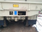
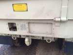
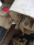
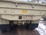
The best spot, IMHO, is to the right of center on the rear bed panel, opposite the pocket for the trailer connector.
I wanted the solution to look "factory" (although I grant that no license plate on an MV can look "factory"), so I copied the method used to mount the trailer plug.

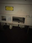
First I cut the hole. Non-trivial, it turns out. I didn't measure, but the panel is somewhere between .125 and .188 thick.
I debated between free-hand plasma, stenciled plasma, Mag-drill and holesaw + grinder as methods of removal.
I didn't have a bit large enough on my magdrill for the radius I wanted so that was out.
I taped the outline of the cutout and started with a holesaw (in hand drill) in the corner, and that clearly wasn't going to cut it (literally).
so I used the hole saw to mark the radii, and switched to freehand plasma. Straights were against straightedge, corners-freehand

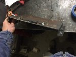
That worked pretty well, but I had to weld up a few over-runs, hence the little welder in the pic. But all in all, it came out pretty well. In the second pic, you can barely see, but I had to notch the bed frame a little, but it wasn't attached to anything at that point, so structurally, no loss.
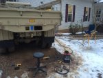
IMG_1976.jpgIMG_1977.jpgIMG_1981.jpg

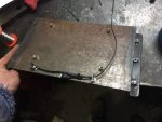
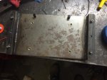
Then on to the bracket. In the keeping of "like the trailer plug method", I wanted a plate with two bends on each side giving an offset of about an inch, with the whole thing a bit bigger than the opening.
I found a suitable piece of 1/8 steel in the scrap pile and got it cut to size.
I have two sheet metal brakes right now. One little one that replaces vise jaws. 8" wide, at that length, max thickness is probably about .030" It couldn't touch the 1/8 plate.
I also have a large one, home brew that fits in a 20 ton press. Should be good to about 3/8'. But that one can't put bends closer than about 3" to each other.
I hate being under-tooled... But bending was out.


So I switched plans to welding and dug out some 1" angle...
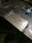
IMG_1979.jpgIMG_1980.jpg


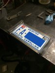
Then for lights, I started with ThoseMilitaryGuys light kit and put it on the plate. Added riv-nuts for the license plate.
IMG_1987.jpgIMG_1988.jpgIMG_1989.jpg

And here is what the plate looks like installed. I still have to replace the SHCS with hex heads to match.
I've also replaced the light kit with a six LED 24v unit from pilotlights.net, that way I don't need the regulator, which I might have already popped.
IMG_1990.jpgIMG_1991.jpg

Overall, I'm quite happy with how it turned out.
 
Last edited:

rustystud

Well-known member
9,071
2,388
113
Location
Woodinville, Washington
Looks good, but your rubber bumper has nowhere to hit when the gate is down. Looks like it goes where your plate is. I guess you can just move them more to the outside.
 

doghead

4 Star General /Moderator
Staff member
Super Moderator
Steel Soldiers Supporter
26,247
1,168
113
Location
NY
Pretty sure they used to contact the bumperettes(that are missing)
 

lino

Member
148
2
18
Location
Wake Forest, NC
Pretty sure they used to contact the bumperettes(that are missing)
Yes, those bumpers hit on the bumperettes (but it's purely platonic)..

Bumperettes, and tailights, are temporarily missing in those pics. In fact they are back on currently. I explored keeping the bumperettes off, but they seem to be worth keeping. The receiver/winch/shackles I'm working on to fit back there will work around them.

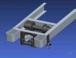
Here's a preview of the unfinished design. Dark grey is new stuff, light grey is stock. Receiver (not shown) will mount in a manner similar to Sewerzuk's...
rear_frame_updates.jpg
Lots of fit checking and winch fleet angle stuff to go. Stress on the unfinished part of the design.
I also have to make the fairlead, and I'm not sure I want to.
I'm toying with putting in a line-spooler http://www.alliedpower.com/auto-advance-line-spooler.html, something like that. One, to wrap the drum properly, and two, to shrink the fairlead size to help fit all that in there.
Right now, the only additional holes in vehicle will be 6 holes on lower frame rails to mount winch plate.
(I normally wouldn't put holes in horiz frame surfaces, since they are the most stressed, but this is outside the driveline mounting area - so less stress)
No welding to vehicle.
I checked the departure angle, and the bumperettes are still the limiter, not the fairlead hanging down. With the receiver in place, it clearly will be affected.
 
Last edited:
Jeepsinker

Well-known member
5,341
329
83
Location
Dry Creek, Louisiana
A line spooler like that would be really nice for the Garwood 10k on the front of our deuces. I'd pay good money for one. Spooling the cable back in properly is such a pain, and even more so by yourself.
 

lino

Member
148
2
18
Location
Wake Forest, NC
Made a little more progress over the last few days...

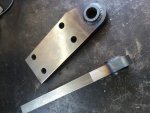
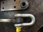
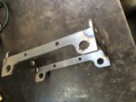
Here are some shackle mounts, that will bolt on rear of frame, using bumperette holes. (hoping to be able to sandwich between bumperette and frame if I can flex bumperette enough).
IMG_2202.jpgIMG_2203.jpg

For reference, the CAD pic is 3 posts up.

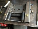
Then I got started on the "vertical Receiver and fairlead" weldment. Here's the fairlead, tacked up:
IMG_2204.jpg

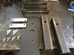
And all the bits that get stuck together:
IMG_2206.jpg

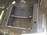
Here it is tacked up (incorrectly), and then (correctly) after welding. I tacked everything with the tig (as I prefer tig welding), but did the real welding with mig as it's much better suited for this size job.
IMG_2208.jpgIMG_2210.jpg

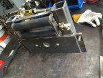
And finally, with the fairlead temporarily assembled, and the pins to hold the lower receiver in place. You can still see the weld seam on the inside of the square tubing, but I broached out the bulk of the weld, so that the mating tube fits nicely.
IMG_2212.jpgIMG_2216.jpg

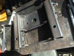
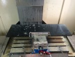
Oh and here's the the plate the winch sits on, coming off the mill:
IMG_2207.jpg

Paint is drying on the parts right now. Hope to get them installed tomorrow and get started on the lower receiver assembly...


ciao
lino
 

lino

Member
148
2
18
Location
Wake Forest, NC
Well, I'm a day or so late posting, but I got that part, and the winch installed.
IMG_2217.jpg

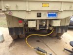
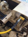
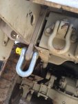
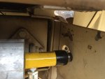
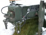
That's what it looks like mostly installed. The power pack/hose is there because I decided to persuade the bumperette to let me put the shackle mount between it and the frame. That puts loads closer (more direct) to frame and then the shackle mount is in double shear (sorta). The following pics show the persuasion. Worked out pretty well/easy (if you have hydraulic persuasion).

IMG_2220.jpgIMG_2223.jpgIMG_2221.jpgIMG_2219.jpg

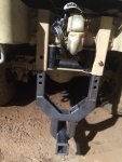
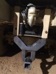
A couple shots of the hitch and fairlead. In all but extreme upward winch angles, the hitch can remain upright. Or just turn out of the way...
IMG_2225.jpgIMG_2224.jpg

And the physical portion of the winch install:
IMG_2228.jpgIMG_2227.jpg

Once I got the "process" down for how to get the winch and plate in and out it wasn't too bad.
Winch had to be lifted in, up, then over the pintle supports between bed rails (above frame), then plate goes in at angle and sits between frame rails (31.5" for 3/8" plate is the longest that will squeeze in). After plate is in, lower winch back down, slide onto plate. 6, 5/8 bolts hold plate to frame. God Bless mag drills!! Forgot to get pics of that step.
No pics of winch lift as it was not ideal. Great care was taken and all went well, but setup was sketchy. Stackup was: Dolly, large plastic storage box, floor jack. On jack was: 4x4 steel tube then steel plate, then winch. It was stable if moved slowly and with care. To roll under truck, there was one path in with less than .5" clearance. Needed to start that high so that jack could raise it above frame rails to allow plate in. Also requires that you can lift ~200# winch 3 feet onto jack.

Winch electric install in progress. Trying to get better idea of which gauge wire/cable to run for power. Winch has 1/0 on it. Seems that for 24v that might be OK. Some have run 2/0. Tried calling Warn, but had no answer. Ampacity on weld charts suggests that 1/0 will be fine. Any advice/suggestions?

Next step is to get lower hitch system built. Design done. Final step is the angle supports from lower receiver to frame (main horizontal load carriers). More on that soon.

Thanks

ciao
lino
 

rustystud

Well-known member
9,071
2,388
113
Location
Woodinville, Washington
Well, I'm a day or so late posting, but I got that part, and the winch installed.
View attachment 549565

That's what it looks like mostly installed. The power pack/hose is there because I decided to persuade the bumperette to let me put the shackle mount between it and the frame. That puts loads closer (more direct) to frame and then the shackle mount is in double shear (sorta). The following pics show the persuasion. Worked out pretty well/easy (if you have hydraulic persuasion).

View attachment 549567View attachment 549569View attachment 549568View attachment 549566

A couple shots of the hitch and fairlead. In all but extreme upward winch angles, the hitch can remain upright. Or just turn out of the way...
View attachment 549571View attachment 549570

And the physical portion of the winch install:
View attachment 549573View attachment 549572

Once I got the "process" down for how to get the winch and plate in and out it wasn't too bad.
Winch had to be lifted in, up, then over the pintle supports between bed rails (above frame), then plate goes in at angle and sits between frame rails (31.5" for 3/8" plate is the longest that will squeeze in). After plate is in, lower winch back down, slide onto plate. 6, 5/8 bolts hold plate to frame. God Bless mag drills!! Forgot to get pics of that step.
No pics of winch lift as it was not ideal. Great care was taken and all went well, but setup was sketchy. Stackup was: Dolly, large plastic storage box, floor jack. On jack was: 4x4 steel tube then steel plate, then winch. It was stable if moved slowly and with care. To roll under truck, there was one path in with less than .5" clearance. Needed to start that high so that jack could raise it above frame rails to allow plate in. Also requires that you can lift ~200# winch 3 feet onto jack.

Winch electric install in progress. Trying to get better idea of which gauge wire/cable to run for power. Winch has 1/0 on it. Seems that for 24v that might be OK. Some have run 2/0. Tried calling Warn, but had no answer. Ampacity on weld charts suggests that 1/0 will be fine. Any advice/suggestions?

Next step is to get lower hitch system built. Design done. Final step is the angle supports from lower receiver to frame (main horizontal load carriers). More on that soon.

Thanks

ciao
lino
Considering where your pulling the power from (battery box) I would go with 2/0 welding cable. There is a outfit on eBay that sells it very reasonably .
 

lino

Member
148
2
18
Location
Wake Forest, NC
Almost done with civy receiver...


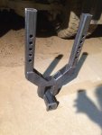
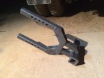
Got the removable lower bracket welded up and fitted.
IMG_2231.jpgIMG_2232.jpg

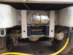
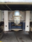
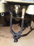
You can see that there are 5 height adjustments, 1.5" apart. The goal was to be about right on the second pin from bottom with NDTs and still be usable with 395s on a higher pin setting.
Pinned up and pinned down:
IMG_2234.jpgIMG_2235.jpg

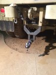
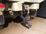
Here's pinned at nominal 12" off ground, and with all the bits in place. Also showing how bracket is just short enough to be installed between ground and fairlead.
IMG_2229.jpgIMG_2230.jpgIMG_2233.jpgIMG_2236.jpg

Welding this was a pain, as expected.
Well, the welding was easy, but having a design with two sliding tubes is a good way to have a non-sliding setup once it's welded. I thought it would be tricky to keep things from warping too much to work when I welded it...

I went thru significant effort on the fairlead bracket to insure that the two outer tubes were parallel. Then I built up the lower bracket with clamps and insured that it still slid in and out easily. It did. Then I tack welded and it still slid well.
Then I fully welded - and I expected this...
As soon as I finished welding, I put it in place, it slid in, but with slightly more effort. Then I took it out and reinstalled, it got worse... then within about a minute, it wouldn't fit anymore.

The nature of that design and the welding pulled the free ends of the tube together. I was careful, and lucky, however in that the two tubes remained in the same plane (if not, it would be much harder to fix!).
So with a few iterations of putting a floor jack between the tubes (one weldment had finished cooling), I was able to coax the two back where they belonged, and now it slides in and out nicely. Pins still fit too!
I think I had to move it about .080" But I didn't measure.

So next, and final, step is to put triangulation bars to take horizontal loads back to the frame (instead of having them twist rear frame crossmember).
 

rosco

Active member
Steel Soldiers Supporter
2,102
27
38
Location
Delta Junction, Alaska
That's a lot of high quality work! The area there around your Pintle is getting very busy. It often does with the addition of even a receiver hitch. I pull an M989 ammo trailer with my M35A2 & found that it works but the addition of 2" of extension gives a little more room. The trailer is otherwise stock.DSCN0009.jpg If you want to maintain the use of the Pintle, its good to keep clearances in mind, especially when backing up in tight spaces.
 

lino

Member
148
2
18
Location
Wake Forest, NC
Well, I've been to busy to post for a bit, but I did keep up with picture progress more or less. So here are some updates:
Finished hitch system
Finished 12v civy trailer plug
installed 395s

For later today is finishing winch wiring...

And the pics:
More on the hitch. I've added tethers to each hitch pin and its lynch pin, but haven't got pics of that.

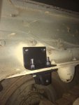
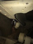
First are the frame reinforcements for the load bars. I used a similar method to the sandwich used for the bump stops.
IMG_2245.jpgIMG_2247.jpg

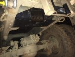
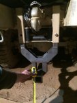
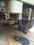
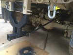
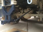
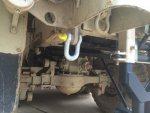
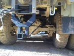
Here are some views of the load bars in the two positions. The idea being that I didn't want to crawl way under the truck to remove the load bars when I take out the hitch. Also needed to be all tool free.
So, pull the rear load bar pin (shown bolted in this pic) and you can move it from the lower part of the hitch to the side of the fairlead for storage when the hitch is out. Two more pins, and the hitch is removed. If I get ambitious later, I may make a set of receiver tubes up under the bed somewhere for hitch storage when not in use, so it's always with the truck.
IMG_2248.jpgIMG_2249.jpgIMG_2250.jpgIMG_2251.jpg

And here are pics of the whole thing, but before I sorted out the pins.
IMG_2294.jpgIMG_2297.jpg

Next post for civy trailer plug and then tires.
 

lino

Member
148
2
18
Location
Wake Forest, NC
For trailers, I wanted to be 12v compatible but also not loose the stock military setup.
So added a 7 pin civy trailer plug.

I'm getting smoother with the plasma torch...
IMG_2311.jpgIMG_2310.jpg

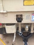
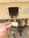
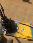
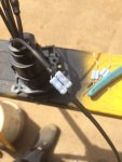
To wire the plug, I just tapped into the military trailer wires. To get a 12V output (since I only have one trailer), I just measured the current draw of my trailer lights (on 12v power) and figured out what size resistor I needed to drop 24v to 12v at that current. Current times voltage gives power, so I had the necessary wattage for those resistors, which I more than doubled, just in case. Wired in and tested, and they work great.

I should note, this is a very cheap and easy fix, but now my plug will only work with 12 LED trailer lights that have similar current draw to mine. That is, it's a specific solution, not a universal solution. Which in this case, is just fine with me.

A couple shots of wiring the resistors
IMG_2307.jpgIMG_2308.jpg

And next post is on the 395s
 

Hainebd

New member
520
5
0
Location
Mays Landing, NJ
This is the nices, most reasonable, practical and cool. But if the hitch is adjustable up/down, the pull bar length will change? How is that accomplished? Did you modify the pintle bolt so max thread engagement with out moving the castles on the nut?
Nice pictures too! Good job!
 

lino

Member
148
2
18
Location
Wake Forest, NC
This is the nices, most reasonable, practical and cool. But if the hitch is adjustable up/down, the pull bar length will change? How is that accomplished? Did you modify the pintle bolt so max thread engagement with out moving the castles on the nut?
Nice pictures too! Good job!
Good catch! The pull bars are turn buckles, so I can change the length just enough to stow them and connect to the lowest position of the hitch. Getting that geometry to work was the trickiest part of all this.

The pintle is now spaced out 3/8 from it's original position (the stuff I put in is sandwiched in there). I checked before I started and the castle nut grooves were so deep that I could still use the cotter pin with the nut 3/8" further out. So all I had to change was to put slightly longer bolts on the two holding the pintle housing, and the 4 that held the inboard mounts of the bumperettes.
 

Hainebd

New member
520
5
0
Location
Mays Landing, NJ
You asked what cable size to use for winch. Need to know amp draw. Warn has charts for all the winches offered. If I was me I use 1O twice form the battery to control box if the winch use is low. If heavy use the 2O. That is a long run of unprocted (fused) wire so protect it some how.
 

lino

Member
148
2
18
Location
Wake Forest, NC
I found a good deal on new 395s so I moved up the timetable on those.
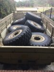
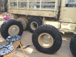
They came with Hutchinson aluminum wheels which is also what I was after.
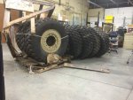
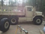
I had them shipped to my office, which has a loading dock... Then loaded into the deuce to drive home. Front end loaded on tractor allowed for unloading.
IMG_2288.jpgIMG_2289.jpg

Peashooter makes very fine MRAP wheel adapters so with those in hand and his valuable advise, off I went.


However, as in nearly all things, I'm cursed with not being satisfied doing things normally... So what I wanted was dish out in the back (for maximum track) and dish in on the fronts. But I wanted all seven wheels to fit in any location so the spare (and any wheel) is universal. That meant I needed air valves on both sides of every wheel...

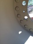
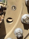
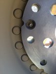
So with some figuring, testing and the like, I found that a valve exactly opposite the stock one on the inside of the wheel would be perfect. So I removed the original valves and (glup) drilled the rest of the way thru the wheel...
(drill size R for the 1/8 NPT of the new fittings) Tapped 1/8 NPT from the inside and installed a 1/8 NPT to Schraeder valve from McMaster. (worth noting is that the stock valves are 1/4 NPT thread, so the drill thru was a smaller size and didn't risk the original threads.) The wheel is more than an inch thick at this location so there is plenty of room to support pipe threads from both sides.

Some pics of the hole before tapping.
IMG_2312.jpgIMG_2313.jpg

The next issue is that I needed the adapter plates to have the lug holes tapered on both sides. They typically aren't, but Peashooter does offer that modification as an option. But I had lined up the work for the upcoming weekend and didn't have time for him to chamfer. So I planned to. The other issue is that the new valve interfered with the adapter plate so I needed to add a new hole in it anyway (and one opposite for balance).

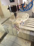
So I made a jig to hold the adapters in my mill and added new holes and chamfers.
Here's a shot of the cutting, and of the new valve in its clearance hole.
IMG_2314.jpgIMG_2317.jpg

Many, many, thanks to Peashooter on this for his fine product and his help on dimensions, tolerances and getting me the info I needed to be able to modify these adapters correctly.

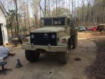
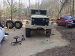
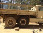
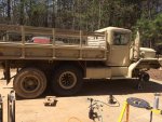
And here are some pics of the first half of the installation. And the humorous ones of the truck half done. (I had to drive it like this to turn it around in the driveway - quite interesting!)
You can also see my new LED headlights...
IMG_2333.jpgIMG_2331.jpgIMG_2329.jpgIMG_2324.jpgIMG_2323.jpgIMG_2321.jpgIMG_2318.jpgIMG_2334.jpg
 
Last edited:
lino

Member
148
2
18
Location
Wake Forest, NC
You asked what cable size to use for winch. Need to know amp draw. Warn has charts for all the winches offered. If I was me I use 1O twice form the battery to control box if the winch use is low. If heavy use the 2O. That is a long run of unprocted (fused) wire so protect it some how.
Good advise, thank you. I had also arrived at 2/0 cable as the choice. Peak current draw is listed at 278A by Warn. The winch has 1/0 cable (it's cut off an MRAP), but only for a few inches. I'll splice to those pigtails as the control box is fully potted on the 18000 military Warn, so the lug connections in there are inaccessable.

As to fuse protection, that's a good idea but tough to implement. Seems like I'd need a 300 or 350A fusible link on the plus side for this. I'll have to look around and see if they exist. The winch has over current protection, but there's nothing to protect the batteries or vehicle from fire if I were to somehow get a short along the 20 odd feet of cable...

Hmm. Noted. Thank you.
 
Top
AdBlock Detected

We get it, advertisements are annoying!

Sure, ad-blocking software does a great job at blocking ads, but it also blocks useful features of our website like our supporting vendors. Their ads help keep Steel Soldiers going. Please consider disabling your ad blockers for the site. Thanks!

I've Disabled AdBlock
No Thanks