• Steel Soldiers now has a few new forums, read more about it at: New Munitions Forums!

  • Microsoft MSN, Live, Hotmail, Outlook email users may not be receiving emails. We are working to resolve this issue. Please add support@steelsoldiers.com to your trusted contacts.

Building Battery / Alternator / Starter Cables for CUCV

number9er

Member
68
0
8
Location
Western NC
As I overhaul the electrical system in my M1009, I'm going to start with the high-amperage circuits: The battery cables, alternator cables, and starter cable. My goal is to make the cables without removing the old ones to measure. I've measured them in place to get a rough estimate for purchasing materials, but I'm hoping to get more accurate measurements before cutting and terminating the new set.

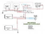
Below you'll see the cables I intend to replace in this process. I'll edit the list as I get better measurements. I also need to add the battery terminals, lugs, and butt connectors.
Batter-Alternator-Cables_alpha2.jpg
 
Last edited:
It may be called overkiĺl by many here but I used 2/0 and 4/0 cable when I replaced all of the large battery cables.Keep in mind as you are building your new cables that none of the ends are steel. Steel is a horrable conductor of electricity.I will never have battery cable issues on these trucks again.I also added a pair of cables routed thru the passenger frame rail in stainless steel tube for power to the rear slave receptical as i had both the cable and the ss tube left over from a hydraulic cylinder plumbing job, the ss tube is to protect the cables from anything that could cut into them causing a short.
 
Last edited:

number9er

Member
68
0
8
Location
Western NC
I considered going bigger by a gauge or so on a few of these links. I think the dogbone cable (from front batt + to rear batt -) seems like a weak link at 4 AWG as per the spec. The short front battery negative lead to the frame is only 10 AWG.

If I do change any of the wire gauge, I want to at least stay strictly to the spec with wire color. The only problem I foresee is sourcing the red/white stripe 8 AWG gen 2 to 12v terminal cable. I'd take it in 6 or even 4 AWG if I could find it. Of course then I would need to rethink the fusible link sizes (10 or 8 gauge I guess?). Fusible links of that size may not even be very effective.
 

tim292stro

Well-known member
2,118
39
48
Location
S.F. Bay Area/California
You will probably have trouble sourcing specific color/stripe combinations - put-ups usually require a large order (think thousands of feet).

My most prevelent complaint is the slave port cable size in relation to the main battery cable size. I also prefer fuses (not circuit breakers) to fusable links, it is more obvious when they blow, and they are much easier to replace.

Also tinned copper crimp lugs vesus clamps, and back-filling the crimp head with solder.
 

tim292stro

Well-known member
2,118
39
48
Location
S.F. Bay Area/California
I bought a Greenlee K09 cable crimper, I waited and found a used one from a pawn shop on e-place. Best $20 I ever spent there - does 8-gauge to 4/0 (0000) ends, in a nice solid hex crimp, and leaves an impression of the cable gauge in the crimp head. If a crimp is done right you get a metallurgical bond just from the pressure - I use solder to seal up any air pocket to prevent moisture corroding the end.

Then I heat shrink seal the whole end with a wire-color-matching self adhesive tube. This shrinks an insulating layer of usually PVC, PFTE, Nylon, etc... with a hot-glue like inner surface. Once the heat-shrink conforms to the shape and surface of the wire and end, the inner face glues itself to the material and creates an air and moisture barrier further protecting the connector and wire. If you write in a circuit number on the heat shrink neatly before shrinking the tube, it will reduce in size and make it look like you have better fine motor skills than you probably do :).

For my money, it would be 4/0 for the battery ties ground-frame and ground-to-engine, between batteries, and to the positive lug of the starter, 1/0 (0-gauge) for the NATO plug (both poles), and then whatever GM sized for everything else, with the understanding that GM sized wires based on cost and what they expected to put on the circuits (so they may need to be re-engineered for your final application). And let's be honest with ourselves, the 80's weren't a great era for GM electrical systems... The starting system is most critical to every other function, so for me it gets the most attention - you wouldn't own and climb into a truck just to watch the wipers run, driving it is what the fun is about!

Make sure that when you do the ground to the frame that you sand the contact surface flat and shinny, star washer to make sure both the cable end and the frame get bitten into, then use an anti-corrosive spray to keep it from getting corroded.
 

number9er

Member
68
0
8
Location
Western NC
Yeah I'm not holding my breath for the red/white stripe. I'll probably tape up the ends in a stripe pattern and shoot it with a can of primer or something. I'm already getting 12ft of 8awg SXL. Might as well go for 20-25.

Any thoughts on using a flag terminal (like this one from NAPA) on the rear battery negative terminal?

I'm not ready to dive into calculating fuses for all of these circuits. Or am I? I may have to rethink that once I decide if I'll increase wire gauge in certain places. I'd like to increase the load capacity of the 12v terminal and fuse block but bigger cable means bigger fuse and the possibility of putting other parts of the circuit at higher risk. At this point I really just want to put a stereo, garmin, and phone charger on a fuse in the fuse block somewhere. Higher load capacity might not be needed if I just get the LMC updated headlight harness and remove that load from the 12v terminal.
 

number9er

Member
68
0
8
Location
Western NC
For my money, it would be 4/0 for the battery ties ground-frame and ground-to-engine, between batteries, and to the positive lug of the starter, 1/0 (0-gauge) for the NATO plug (both poles), and then whatever GM sized for everything else...
So you'd keep the entire 12v system and both alts on 8 AWG?
 

tim292stro

Well-known member
2,118
39
48
Location
S.F. Bay Area/California
The fusible links in the diagram you published in the first post are meant only to protect the wiring of the alternator power lines - that's simple, no calculation required, pick a fuse at the output rating of the alternator. In the diagram, I don't like that the starter line goes through a power block, that's two more connectors (from the battery, to the starter) and a power block that can all add corrosion failure points. The starter circuit, and the NATO jump port, are very high current circuits. Yes after the starting/charging circuits, the glow plugs are probably your next highest load, then your headlights, your wiper motor, your brake lights and turn signals, and finally your parking lights. The blackout lights are LED on the CUCV (except for the blackout driving light, which draws about as much as one parking bulb).

I used to do car stereos in the mid 90's, I'd recommend a secondary fuse block rather than messing with your original wiring at all. You can convert the radio power port behind the passenger seat to a 12-volt only to run loads off of, or even better leave it 24Volts and run a 60Amp Vanner off of it to charge an auxiliary battery just for your new accessories. This prevents your new loads from sucking your starting batteries dry, and spreads the charging load over both alternators.
12V_Second_Bank_Vanner.jpg

So you'd keep the entire 12v system and both alts on 8 AWG?
Good clean 8Gauge copper wire has a resistance of about 0.0062996Ohms per foot (this is "wire loss"). Assuming a 20 foot run (10-feet there, 10-feet back), this is a total resistance of about 0.0126Ohms, which in a 28.8Volt electrical system with 100Amps current (CUCV alternator rating) works out to about 4.5% loss end-to-end. It's under 5%, so yes I would consider it acceptable, 6Ga would be better yes, but that would be your decision:popcorn:.

Again the starting circuit is the highest pulse load, the NATO port is intended to be part of a starting circuit.
 
Last edited:

number9er

Member
68
0
8
Location
Western NC
I like the Vanner idea. The radio power port behind the passenger seat is long gone but I could sort that out. I think that would all have to be a future improvement though.

You got a great deal on that crimper. That's anoher thing I'm going to have to figure out. I figured I would use solder terminals for the battery ends but I don't currently have the tools for the lug ends. And I'm hoping this is the last set of cables I build for a long time.
 

tim292stro

Well-known member
2,118
39
48
Location
S.F. Bay Area/California
Solder terminals may work, but they have to be done right - if it's your first time, I'd recommend finding an electrician's shop to have them do the cable ends for you.

If you were local, I'd just stop by and do them for you, but it would be a drive... If you still haven't done them by May, drop me a line I might be in your area.
 

number9er

Member
68
0
8
Location
Western NC
Thanks Tim. I might get a replacement for the dogbone/12v lead assembly on that auction site and until I can decide what to do about the rest of it. I've soldered miles of tiny wires but nothing near the size of a battery cable. Hopefully, cleaning all the connections in the charging circuit will fix my gen 2 light issue. Either way these cables are in bad shape and need to be replaced.
 

MarcusOReallyus

Well-known member
4,524
811
113
Location
Virginia
Try these guys: http://www.bestboatwire.com/custom-cables/custom-battery-cable-assembly

Build your own. It will be crimped, not soldered, but the prices are good and the quality looks very good to me. I got mine with clear heat-shrink on the terminals so I can see if anything is getting funky in there. Here are some pics of the cables I got from them.

As for the soldering, a properly done crimp beats a badly done solder joint every time. If you don't have the tools to get the job done, go with crimping or have it done for you.
 

tim292stro

Well-known member
2,118
39
48
Location
S.F. Bay Area/California
It should also be mentioned that the type of crimper you hit with a hammer does a crappy job.

Big wire and teminals need big heat to solder, a propane torch would probably do it well for you, but it will take practice.
 
Last edited:

number9er

Member
68
0
8
Location
Western NC
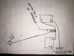
Yeah, I have a propane torch and that was the plan. That Best Boat Wire site that Marcus mentioned is looking very promising though. I don't see where you could order the front + to rear - to 12v bus terminal cable, though I could probably call. I have some ideas of how I could remedy that anyway, and one would give me a good place to put a breaker or fuse to the 12V bus bar. Question: Would it be advisable to use one side of a fuse block or breaker as a junction between the batteries? I plan to use at least 1/0 awg cable. The other side of breaker or fuse block would go by 6 awg to the 12v bus.
IMG_0172.jpg
(I know I left the small front - to frame ground lead off. I suppose I'd lug that on the terminal with 8 awg or something.)
 

tim292stro

Well-known member
2,118
39
48
Location
S.F. Bay Area/California
It would be preferable to use either the pass-through flag type lug you linked from the Napa website, or to make the branch from one of the batteries (have you considered stud terminal batteries?). Doing a mid-span connection is adding two more corrosion points to your high current path (starter).

It is however your truck, so if you have different ideas or aren't sharing everything you plan to do with this, you can always do it your way, I'm not one of the "haters" - it would be hypocritical of me [thumbzup]

If you get creative, you can do a stud-terminal battery, and use a copper plate "strap" to connect the two batteries (positive-to-negative), then put a few bolts in the plate to create a tripple ANL fuse-block for the lower and upper alternators, and a 12V feed to the vehicle. Have a shop powder coat anything that you don't want to be conductive and you get a slick custom power distribution system. It depends on what you are trying to solve, what your budget is, and how much time you want to spend messing with this...
 

number9er

Member
68
0
8
Location
Western NC
No, trust me. I like the way you think. The copper plate strap would be niiiiice. But I'd have to reconfigure everything including the battery holders. Budget is a bit of an issue, at least until I can get a few other things fixed. I'm sharing everything that's on deck to do now. My future plans for the truck will change so many times, there's no point in sharing them yet. I'll stay on the drawing board with this, and report back with what I come up with.

I just spent an unacceptable amount of time going through your CUCV Crew Cab thread. I may have to work overtime next week to make up the time. I can't wait to see some final product pics.
 

number9er

Member
68
0
8
Location
Western NC
Today I went to a local powertrain shop that advertises building custom battery cables. For the dogbone interconnect, the guy there recommended a 2/0 cable that had pre-made with a regular battery terminal on one end and a terminal with a battery post on the other end (for the 12v feed). That cable was $36, and a ground strap I was looking at was another $24. That still leaves a bunch of cable I've yet to price out. So I told them, I'd do some more accurate measurements and come back. I left without any new cable.

I'd like to go back and visit Tim's copper strap suggestion. Since my batteries, in the original battery trays, are at different heights, I'm thinking I could have a strap bent at right angles at the ends to account for that.

And as long as I'm starting to get out of hand with what started as a stock rebuild, if I intend to bypass the glow plug resistor bank and bulk up the 12v feed cable, should I be considering a battery equalizer? Would a 100 amp Vanner survive on the starting circuit?
 
Last edited:

tim292stro

Well-known member
2,118
39
48
Location
S.F. Bay Area/California
If you are keeping the dual batteries and alternators under the hood, the 12V alternator removes the need for a Vanner/equalizer there.

If the 24V glow plug system is working, I'd actually recommend leaving it alone. There aren't any good 24V glow plugs really available, and if you draw from one battery for the plugs, it does reduce your total cranking power too (since you get the weakest remaining current of both batteries). Yes, the resistor is wasteful, but doing a proper 24-to-12V voltage regulator would be cost and space prohibitive.

If you are really thinking of doing the copper strap, I'm going to recommend that you move to Group 31 batteries at the same time and put them both in the front battery tray. This will make it possible to secure both batteries with a single tie down strap, and reduce any battery to battery movement that might screw up the copper plate. A company I have personally used for a few copper fabrication projects is Storm Copper. They will do all of the bending, drilling and powder-coating you want (and at a price). Take a look at their site to get an idea of what raw material costs before you jump in head first. :)
 
Top
AdBlock Detected

We get it, advertisements are annoying!

Sure, ad-blocking software does a great job at blocking ads, but it also blocks useful features of our website like our supporting vendors. Their ads help keep Steel Soldiers going. Please consider disabling your ad blockers for the site. Thanks!

I've Disabled AdBlock
No Thanks