Pain
New member
- 2
- 1
- 3
- Location
- Pittsburgh, PA
Greetings all!
I am looking for some help with fixing a MEP-804A genset that's been a real trouble for the past several weeks.
For starters it will turn over and run, however after you release the master switch from the start position, the "under voltage" fault lamp will illuminate. This will remain lit until the generator is turned off. If you adjust the voltage or frequency dials, little changes aside from the Hertz, of which will stay below 50 on the respective gauge. Moving the voltage dial causes nothing to change the reading/output, and it hovers around 12-16 volts. The only way to get the gauges to show something close to the normal range/ expected readings is upon startup while holding the master switch in start.
Some interesting notes I can include:
The gauges themselves for the Voltage and Frequency (Hz) readings work fine, and I've done testing on them according to the manuals I have on hand here. I can always check them again, however.
The AC Circut interruptor switch will not remain closed, it will however light the indicator light if you hold the switch yourself.
Another finding I had was when I connected a piece of diagnostic equipment to the testing port, it causes the "under voltage" lamp to go away after starting it up, and instead now causes the "over voltage" lamp to illuminate. The generator will also shut itself down immediately in this condition, unless you hold the master switch in the start position, but when you let go of it will shut down once again. This condition only occurs when you have the diagnostic piece plugged into the port. Once you remove it and restart the generator, the "under voltage" scenario I mentioned earlier will come back, the "over voltage" lamp will not light, and the generator once again will continue to run once the start switch is let go of.
I will provide all the information I can on the piece of equipment that is requested to help things along, if anyone has any idea as to what is going on with it.
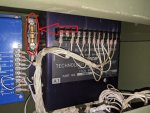
For now I can report that I have replaced the master switch, voltage regulator, the K17 relay, and voltage dial potentiometer. All of which have not changed anything The electronic components all are made by TRC, as I know that mixing from the other company can cause a myriad of problems. I have visibly inspected the wiring harnesses and cannot find any chafed or broken/exposed wires. At one point I held the AC circuit interrupter switch closed and checked the output terminals, where I got a reading of roughly 15 volts.
I have been through the manuals on so many occasions that I am running out of ideas on what to continue testing/troubleshooting unfortunately. I am still new to working on generators, and this community and it's posts have been a phenomenal source of learning and help. I can hope to hear from some of you if you have any ideas/something to try out!
Many thanks for reading, and any help is appreciated.
I am looking for some help with fixing a MEP-804A genset that's been a real trouble for the past several weeks.
For starters it will turn over and run, however after you release the master switch from the start position, the "under voltage" fault lamp will illuminate. This will remain lit until the generator is turned off. If you adjust the voltage or frequency dials, little changes aside from the Hertz, of which will stay below 50 on the respective gauge. Moving the voltage dial causes nothing to change the reading/output, and it hovers around 12-16 volts. The only way to get the gauges to show something close to the normal range/ expected readings is upon startup while holding the master switch in start.
Some interesting notes I can include:
The gauges themselves for the Voltage and Frequency (Hz) readings work fine, and I've done testing on them according to the manuals I have on hand here. I can always check them again, however.
The AC Circut interruptor switch will not remain closed, it will however light the indicator light if you hold the switch yourself.
Another finding I had was when I connected a piece of diagnostic equipment to the testing port, it causes the "under voltage" lamp to go away after starting it up, and instead now causes the "over voltage" lamp to illuminate. The generator will also shut itself down immediately in this condition, unless you hold the master switch in the start position, but when you let go of it will shut down once again. This condition only occurs when you have the diagnostic piece plugged into the port. Once you remove it and restart the generator, the "under voltage" scenario I mentioned earlier will come back, the "over voltage" lamp will not light, and the generator once again will continue to run once the start switch is let go of.
I will provide all the information I can on the piece of equipment that is requested to help things along, if anyone has any idea as to what is going on with it.
For now I can report that I have replaced the master switch, voltage regulator, the K17 relay, and voltage dial potentiometer. All of which have not changed anything The electronic components all are made by TRC, as I know that mixing from the other company can cause a myriad of problems. I have visibly inspected the wiring harnesses and cannot find any chafed or broken/exposed wires. At one point I held the AC circuit interrupter switch closed and checked the output terminals, where I got a reading of roughly 15 volts.
I have been through the manuals on so many occasions that I am running out of ideas on what to continue testing/troubleshooting unfortunately. I am still new to working on generators, and this community and it's posts have been a phenomenal source of learning and help. I can hope to hear from some of you if you have any ideas/something to try out!
Many thanks for reading, and any help is appreciated.