• Steel Soldiers now has a few new forums, read more about it at: New Munitions Forums!

  • Microsoft MSN, Live, Hotmail, Outlook email users may not be receiving emails. We are working to resolve this issue. Please add support@steelsoldiers.com to your trusted contacts.

Looking for V100 chassis pics

M813rc

Well-known member
Steel Soldiers Supporter
4,200
3,176
113
Location
Near Austin, Texas
Excellent work! Coming along very nicely.

I see you even have the drain plugs. The big one sits directly under the engine oil pan so it can be drained.

Cheers
 

Paweł

Active member
47
137
33
Location
Poland
Hello!
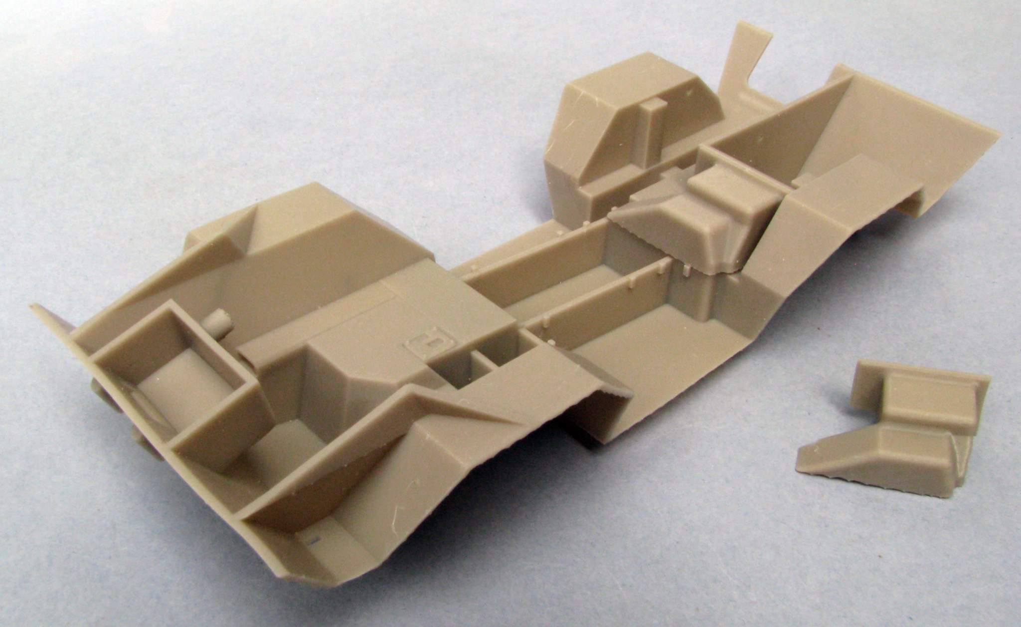
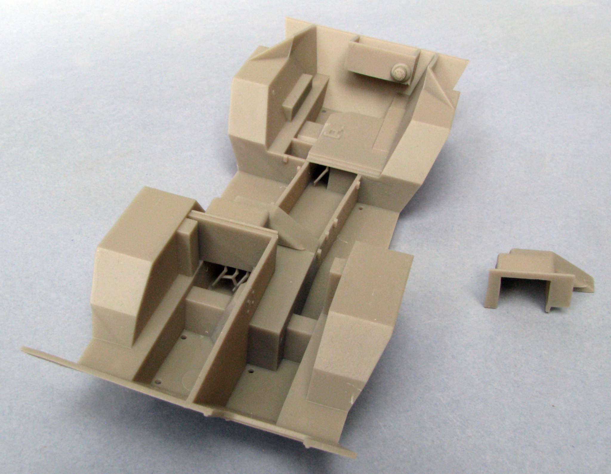
Here are the photos I promised:

chassis11.jpg

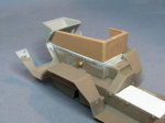
As you can see I got a spare tranny cover from the printer. I plan to make the tunnel cover and the toolbox cover from styrene plate:

chassis12.jpg

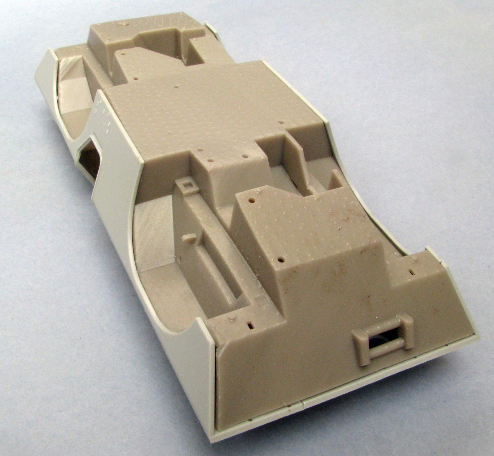
Most important would be if it fits - that is if I got the dimensions right. Luckily it's not so bad:

chassis13.jpg

The parts are usable with some filling on the front and on the surfaces where the support structures attached. The printer also had to make a few holes in the part, I plan to plug them with styrene rod. If I printed the parts on Shapeways the last two problems wouldn't be there.

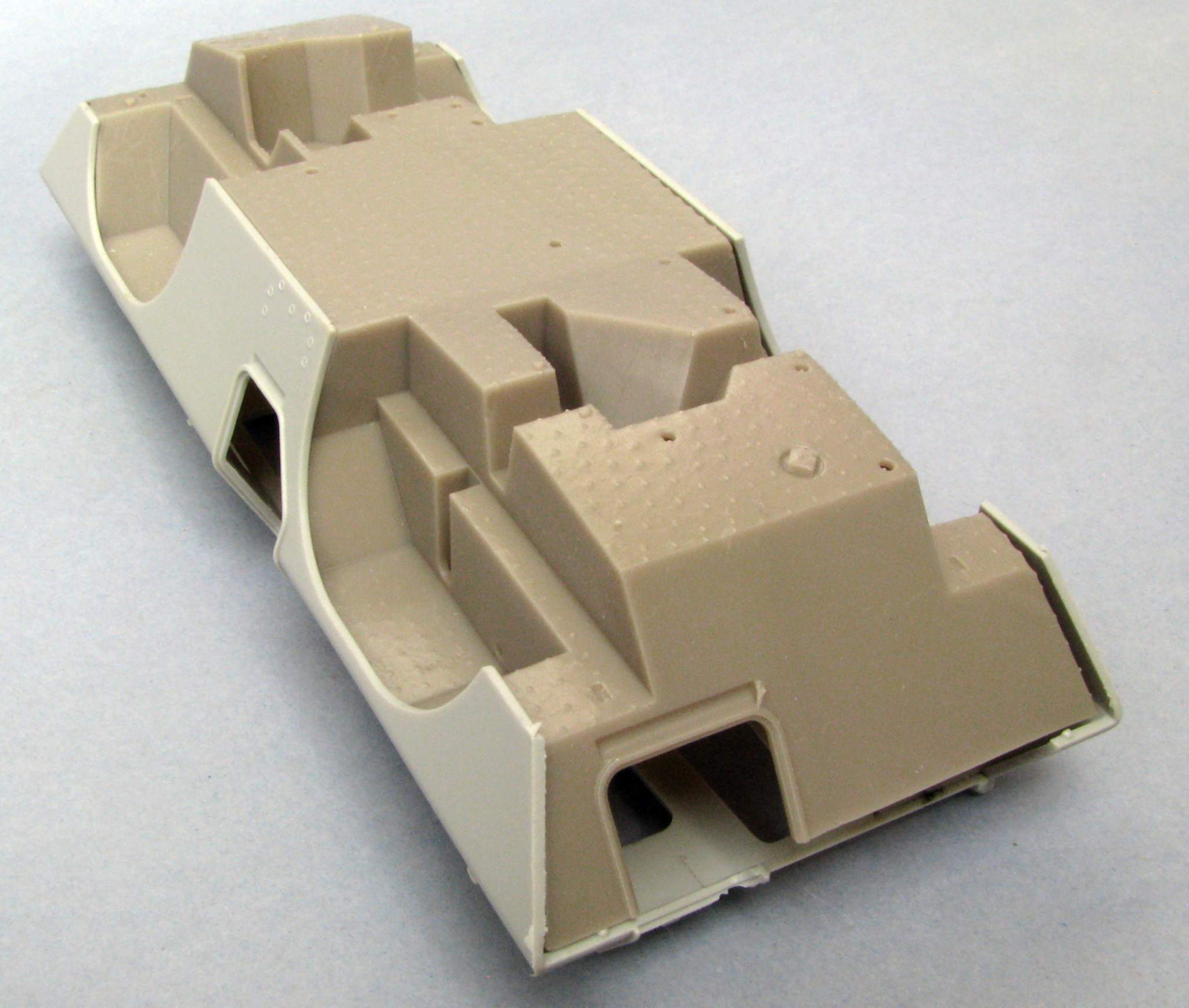
The rear plate has the worst fit:

chassis14.jpg

Looks like while designing it I missed about 1,5mm of height - I plan to fix it in the next version.

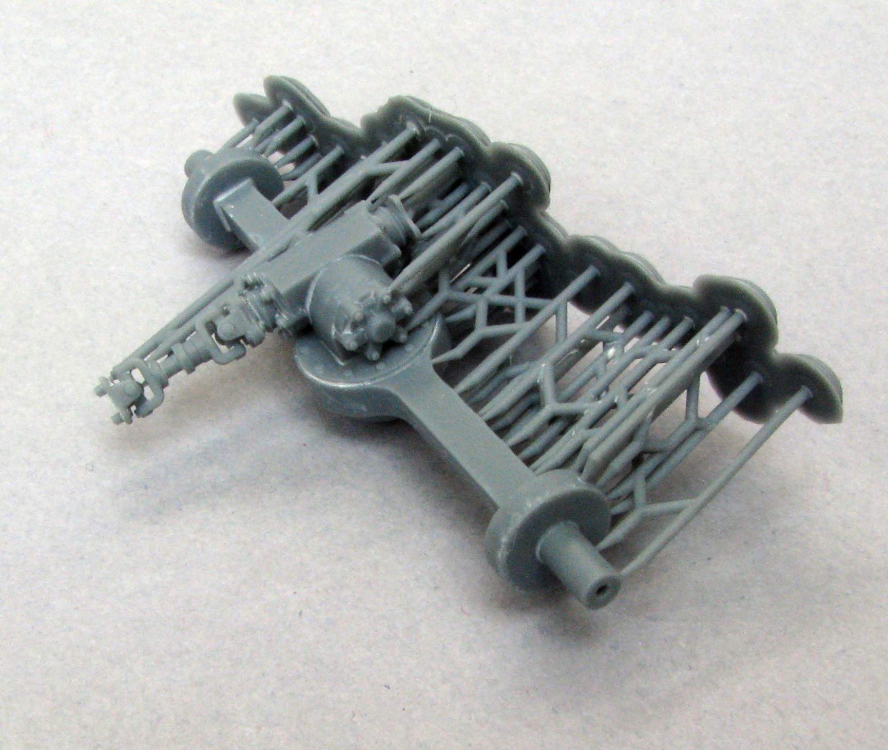
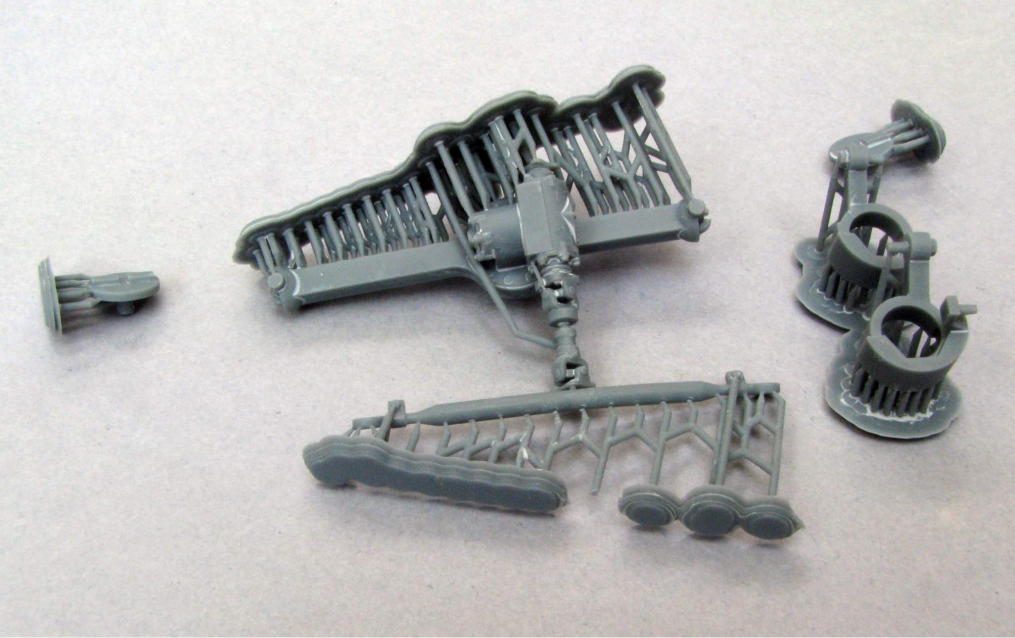
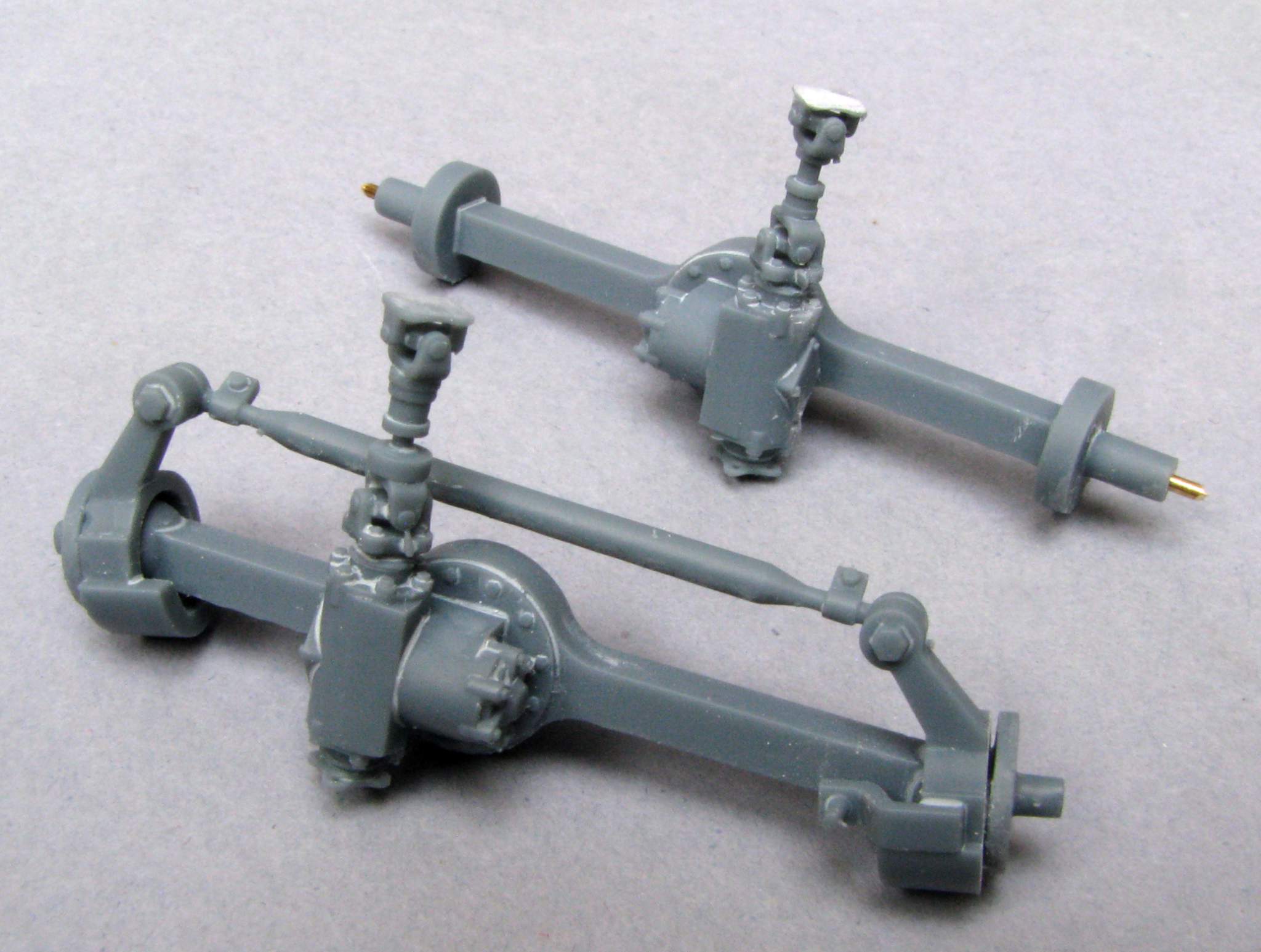
I also got my axles printed, right out of printer they look like this:

Rear axle:

axle01.jpg

Front axle:

axle02.jpg

Both axles have a hole right through to stiffen them with steel wire and hep them from bending under stress and heat. Front axle offers to have the front wheels poseable as "steered" to left or right.

The above parts will most probably soon be available on Shapeways, in case somebody needs them.

Thanks for looking, have a nice day

Paweł
 

Paweł

Active member
47
137
33
Location
Poland
Thanks a lot for your kind words, Rory! Like I wrote, without your photos I couldn't do it!

I removed the support structures from the axles, reinforced them with wire (it’s brass after all, not steel) and I have dry fitted the front axle. Let’s see if I can keep the wheels movable or if I will have to glue them in some position:


axle03.jpg

Thanks for looking and have a nice day

Paweł
 

Paweł

Active member
47
137
33
Location
Poland
Hello everybody!
I'm workin' on the interior now. I'm using parts of the Czech MMK interior kit. The steering box was especially funny to build:
1714946833984.png

The rear looks like this:
1714946871898.png

Thanks for looking and have a nice day
Paweł
 

Paweł

Active member
47
137
33
Location
Poland
Thanks a lot, Rory!
One question - one vet who used M706E2 in Vietnam mentioned a master kill switch located under the drivers seat, do you have something like that on your machine? Maybe you have a photo of it?


I've been working on the interior. First I painted everything Tamiya grey primer:


1:35 M706 Commando by Pawel

I had to literally cut corners on the front grenade boxes to squeeze them in on their locations.

Then I painted everything Seafoam Green - the paint is actually called APC Interior Light Green by AK Interactive. I have also made some of the crash pads out of masking tape painted black:


1:35 M706 Commando by Pawel


I also started working on the instrument panel, I had to scratchbuild it. I started with thin styrene sheet, I put some holes in it and bezels out of thin copper wire:


1:35 M706 Commando by Pawel


Then I made an underlay with instruments and painted it:


1:35 M706 Commando by Pawel


And that would be it for now - thanks for looking and have a nice day


Paweł
 

M813rc

Well-known member
Steel Soldiers Supporter
4,200
3,176
113
Location
Near Austin, Texas
The model is looking great!

I've not heard of a master switch around the driver's seat, the standard location is in the tunnel next to the slave port.
There is a power switch on the instrument panel to power up the fuel pump, lights, and other accessories.

This doesn't necessarily mean the chap you talked to wasn't driving a locally modified vehicle, but it wouldn't make much sense to run all that extra heavy wire up front just so the driver could turn the switch on/off from his seat.

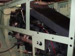
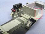
The item in your picture I've circled in red is the slave port. If you are not familiar with them, there is a screw-on cap over a large electrical plug that you attach a heavy set of cables to for jump starting (slaving in military terms) the vehicle from another. It is wired directly to the batteries and the starter, and the master switch is just to the left. In standard American practice, up is on, down is off (the opposite of what I grew up with in Europe!).

I'll look for better pictures in my files, but the ones attached show the switch itself, hopefully clearly enough.
The cables and clamps you can see in the lower part of the large picture are external power connection for testing the starter, they are not standard parts. ;)

Cheers

interior03b.jpg ss4209 - Copy.jpg ss4210 - Copy.jpg
 
Last edited:

M813rc

Well-known member
Steel Soldiers Supporter
4,200
3,176
113
Location
Near Austin, Texas
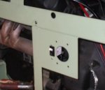
I neglected to mention - the switch and slave port are hard mounted to the engine bay framework. There is a square hole in the cover panel, just big enough to clear both.

Cheers

ss1773 - Copy.jpg
 
Last edited:

Paweł

Active member
47
137
33
Location
Poland
Hello Rory!
Thanks a lot for the explanations and for more very useful photos! I hope I can have an update on my model soon.
Have a nice day!
Paweł
 

Paweł

Active member
47
137
33
Location
Poland
Thanks a lot Rory, it really means a lot to me!

And I have another update on the interior. I have finished the radio:


1:35 M706 Commando by Pawel


Here's how it looks like from the rear:


1:35 M706 Commando by Pawel

And after adding some seatbelts, the lower part of the interior is kinda done :)


1:35 M706 Commando by Pawel


So I started working on the upper interior - I started fitting out the kit's shell with some gun ports and vision blocks made out of thin styrene sheet:


1:35 M706 Commando by Pawel


There are also some more small details like the flashlight holder or the copper wire grab handles. I'll add some more after I paint the insides seafoam green.


Thanks for looking and have a nice day!


Paweł
 

M813rc

Well-known member
Steel Soldiers Supporter
4,200
3,176
113
Location
Near Austin, Texas
That is absolutely wonderful!

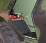
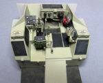
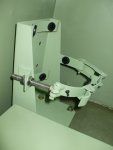
I don't know if you already planned to add it, but here are some details on where the engine fire suppression bottle fits in that cubby I have outlined in red on your model.
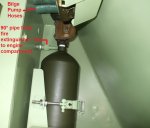
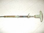
The bottle is activated by a cable that runs along the inside corner of the roof to a T-handle behind the driver's left shoulder. It runs through the roof cross frames. The handle is usually painted red. To operate, the driver can reach above and behind his shoulder with his right hand and pull forward.

That original cable is one of the many detail bits I cleaned up, made work, and put in my V100. Really quite enjoyable work.

Cheers

interior06b.jpg FireEx Cubby.JPG FireEx 72c.jpg FireEx bracket.jpg interior09.jpg FireEx Pull Handle and Cable.jpg FireEx Pull Handle.jpg
 

M813rc

Well-known member
Steel Soldiers Supporter
4,200
3,176
113
Location
Near Austin, Texas
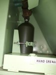
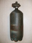
Here is what the fire suppression bottle looks like out of it's bracket.
And two actuators.

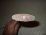
The actuator back screws onto the larger fitting on the bottle, the metal hose into the engine bay screws onto the smaller fitting.

The cable from the drivers seat connects to that lever on the actuator and flips it to the "fire" position.

Cheers

FireEx Bottle.jpg FireEx Actuator.jpg
 

Paweł

Active member
47
137
33
Location
Poland
Hello Rory!
Thanks a lot for your comment!
Yes, I planned to add the third fire extinguisher, but I wasn't aware of the cable and the handle - now I also want to add those. Pity that the handle almost surely won't be visible after I close up the hull. Thanks also for the close-up on the actuator, something like that would be hard to find on the net! I would like to make the bottle red, to add some visual interest to the model. I've seen it like that in the Squadron book. Would it be correct for the Vietnam era? Why is your bottle black?
Thanks again and have a nice day
Paweł
 

M813rc

Well-known member
Steel Soldiers Supporter
4,200
3,176
113
Location
Near Austin, Texas
I thought you probably were going to add it, seeing all the other intricate detail you have put in.
As regards the pull handle, it might be visible looking in the top hatch, or through a side door. And you'll know it is in there. ;)

My bottle is actually OD green. It was NOS in a box (new old stock, as in it was still unused and in the factory box, but dating from 1971).
I had another, that ratty looking green one, which came out of another V100 that colour, so that's how I kept mine.

The bottles came in either green or red, and there seem to be no rules for installing either colour in service, they just put in whatever colour bottle came out of the box.
I had a red bottle too, gave that one to either Dave (HellonwheelsV100) or JimK. We traded a lot of V parts with each other since we were all doing restorations at the same time. Jim got the second actuator in the picture. I don't remember who got the other green bottle.

Even though all my fire extinguishers are originals from the early 1970s, all passed inspection at a fire company, so all are filled and working.

Cheers
 
Last edited:

Paweł

Active member
47
137
33
Location
Poland
Hello Rory!
Thanks a lot, that's an interesting detail that would otherwise be hard or very hard to find on the net.
Could I ask you one more thing? How did you route the cables to the intercom boxes in front, next to the driver and "shotgun"? I would like to do some cabling there, but I have problems figuring it out.
Thanks in advance and have a nice day!
Paweł
 
Top