• Steel Soldiers now has a few new forums, read more about it at: New Munitions Forums!

  • Microsoft MSN, Live, Hotmail, Outlook email users may not be receiving emails. We are working to resolve this issue. Please add support@steelsoldiers.com to your trusted contacts.

Electrical system

Redleg130

Active member
60
132
33
Location
Kansas
This project is very tedious. Everything is a tremendous pain in the backside. It is worth doing as I am finding corroded, worn, and vulnerable items pretty much everywhere so its good that this system is getting attention.

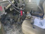
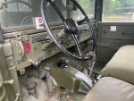
Not electrical, but this has bugged me for awhile. The knock out for the winch lever is just open, and I can't find a cover for this. I made one from thick rubber, using a dremel to cut a deep groove in it so it holds, the backside has adhesive so it should hold.

e23.jpg

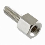
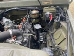
The junction box from Amazon will likely work pretty well, its fairly sturdy and fits on the (I think) regulator mount. I did need a piece of sheet metal and generally my garage has a magical property of having bits of scrap that meet whatever need I have, but it took a bit for this one. I did end up cutting up an old washer/dryer cover plate for the sheet metal, which took awhile to shape but it will work.

e24.jpg

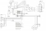
With a place to connect the various wires, I can start actually wiring stuff up. I won't reuse any of this wire, but I am leaving it until I replace it so I have some reference for what connects to what. Replacements will be in loom, I started with key ignition set and am very happy with the protective wrap plus fabric tape combo

e22.jpg

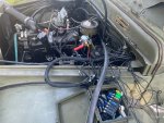
I did run into a snag, the starter solenoid post does not have enough room anymore and I am not sure what to do. The thicker battery cable is good but the alternator and two ring terminals need to go there too. One ring going to ignition via ballast and the other going to fuse box. Do they make a solenoid with a longer post?
 
Last edited:

John Mc

Well-known member
204
291
63
Location
Monkton, VT
Is there no kind of electrical terminal duplicator or splitter that will work? (Something like what you see on modern car battery terminals, where the main connection goes to the batter post, but the clamp also has one or two smaller terminals to piggyback other wires on it.)
 

G744

Well-known member
Steel Soldiers Supporter
1,593
3,494
113
Location
Hidden Valley, Az
A special nut is made for joining two pieces of 'ready-rod' or 'all-thread' in 5/16NC or 3/8NC thread.

Maybe use one of those, with the high current lugs on the first thread, and the others under a short cap screw.
 

Redleg130

Active member
60
132
33
Location
Kansas
Its Cortez burning his ships time.

Got the open questions open regarding what connects to what (which did match the wiring diagram unsurprisingly) but a couple parts like the foot dimmer didn't have markings so I did want to trace things like that. With the last bits mapped out, I was able to remove the last of the old wire.

e25.jpg
e26.jpg

Stud extender looks like exactly what I would prefer, thank you for the term. Busbar is a possibility too, but ill try stud extender first. Not knowing terms makes it hard to find things :v

I did get a wire wrapping loom with fabric tape and I am very happy with how that ends up, the bundles are padded a bit with it.
e27.jpg
 

Redleg130

Active member
60
132
33
Location
Kansas
Thought I would show AF8 tool use, the 4 way crimper, on packard shells. This covers the 'male' end, ill post females later. This seems correct, based on looking at disassembled originals, but if there are errors, please do correct me.

e28.jpg
e29.jpg
e30.jpg
The rubber shell goes on the wire first, followed by the white insert. The metal connector can only fit in one way to the white insert, ensure its oriented correctly before crimping. The more narrow end will face away from the crimp on the white insert.

the insulation should be against the metal connector with the exposed wire taking the entire space in the crimping area. You can see the wires poke through the other side if its long enough.
There are two sides to the metal connector, an end with an external sleeve at the top, and an end without this external sleeve. You can see the orientation in the first picture. This sleeve does not like going through the AF8 (4 way crimp) tool, but it will. I found it easier to insert the connector into the AF8, then the wire, that way I just have to wrestle it out in one direction instead of both ways. Crimping takes considerable oomph, but it does make a solid crimp.
e31.jpg

When complete it will look like this
e32.jpg

The completed connector
e33.jpg

Making the tags - light taps are sufficient, too much hammer and it will weaken the tag
e34.jpg

And wrapping them - I am surprised how easy it is to wrap these, and how sturdy they are when in place.
e35.jpg

This set of connectors I assume are original, its interesting how durable these connections are. I was able to recover three out of four parking lights, the last one had screws so corroded they snapped even after overnight in penetrating oil. I found a replacement at Big Mikes for 70ish.
e36.jpg

Started and ran the engine to get fluids moving, nothing but ignition key to ballast and coil are connected but its good to know at least that works. I still have a long way to go with the rest of the wires.
e37.jpg
 

Redleg130

Active member
60
132
33
Location
Kansas
Attached is what I ended up with, can anyone review the fuse selections and recommend changes? These are my best guesses and I am having trouble finding references.
 

Attachments

Redleg130

Active member
60
132
33
Location
Kansas
Got the last of the connections made and tested, to my surprise everything works.

I used garden hose as 'conduit' for the wires going to the tail end. The old wires were rubbed through in spots, the hose should protect the new ones and I will lash it down more securely.

I wouldn't recommend this project unless you really have to, it really took alot of effort. I do have a much better understanding of whats what now. definitely not an expert, but I do have a clear picture of the electrical system.

I used 500ft of wire, somewhere under 70 packard shells, a bag of packard splices, a couple boxes of ring connectors and a box of disconnects/spade types. 500 foot is probably excessive, I made 'service loops' in case I need to mess with it later.
 

Attachments

Last edited:

Redleg130

Active member
60
132
33
Location
Kansas
This project was successful in that it works and I think it will be durable. I am not completely happy with the outcome, it isn't as tidy as I would like. I can fix this problem, but ill save it for later since I do not have any vulnerable wires and it functions. Ill waste some connectors doing this which isnt the end of the world, but its the cost of learning I suppose. My lessons learned for this project:

I approached this project not knowing what to expect or understanding the systems, I attempted to do this 'in place' which resulted in excess wire since I wasn't sure in some cases where things would land. If I had to do over again, I would wait to crimp connections on ~after~ I completed a bundle which would prevent the problem of uneven bundles. Laying out a bundle and trimming it if needed after everything was laid out would have been preferable. Once neat, discrete bundles were in place and trimmed, wrapping and placing these then making the connections would have resulted in less excess wire. You can see this excess wire in the photos e38 and e41, not terrible, but not professional work.

Garden hose I think will work great as a durable wire protection for undercarriage bundles and it wasn't too hard to work with. I cut outdoor hose to length, and cut it open for the length of the section to get the wire inside. I suppose you could fish tape it through, but wrapping the hose in harness tape after putting wire in cut hose accomplishes the goal of padding wire bundles from abrasion. I also plugged the ends with coaxseal (a moldable plastic like material) to prevent water getting into these.

I should have drawn out bundles (instruments, ignition key, 3 lever switch, taillights, headlights, brake sensor) with their destinations before running sets. This diagram would differ from schematic as it would be physical connections rather than electrical. This would have helped with better estimates of individual wire lengths since not all wires in a bundle will be the same length.

The terminal/fuse box from amazon (seen in photo e38 and e41) works well, but the large number of wires going in gives little room - but its enough. 6x6x4 are outside dimensions. It does fit in the regulator mount next to the oil filter.

I used "MGI SpeedWare Woven Mesh Split-Sleeve Wire Loom" and was really happy with it in conjunction with fabric harness tape. Wire bundles are protected from abrasions and it looks neat/tidy. This brand is fairly thick and the material appears to be durable.

Wire tags are really handy, I am glad I used them. Easy to use and prevented issues with identifying individual wires.

I ended up with a handful of tools to replace my basic set of wire tools. I got Klein strippers and crimpers, my old crimpers could not make satisfactory crimps. Auto wire strippers were also very helpful.

In any case I am back on the road after several tests and glad to be done.
 

Attachments

Top