• Steel Soldiers now has a few new forums, read more about it at: New Munitions Forums!

  • Microsoft MSN, Live, Hotmail, Outlook email users may not be receiving emails. We are working to resolve this issue. Please add support@steelsoldiers.com to your trusted contacts.


Glow Plug Relay Rewiring help needed

Warthog

Moderator
Super Moderator
Steel Soldiers Supporter
13,775
227
63
Location
OKC, OK
The GP Controller uses the tempature sensor on the driver side rear head.

TM 9-2320-289-20p, Figure 19

--------------------------------------------------------------

The Hot Idiot Light used the switch on the driverside front head

The Cold Advance switch is on the passenger rear head.

TM 9-2320-289-20p, Figure 46


The sensor will give a variable reading. The switches are on or off.

************ Edited to give the correct manual number ***************
 
Last edited:

UncleSam

New member
58
3
0
Location
Anniston Alabama
The GP Controller uses the tempature sensor on the driver side rear head.

TM 9-2320-289-20, Figure 19

--------------------------------------------------------------

The Hot Idiot Light used the switch on the driverside front head

The Cold Advance switch is on the passenger rear head.

TM 9-2320-289-20, Figure 46

Thanks for the info, you guys make it a whole lot easier for dummies like me...[thumbzup]
 

Warthog

Moderator
Super Moderator
Steel Soldiers Supporter
13,775
227
63
Location
OKC, OK
So where are you on the wiring cleanup? Ready for the next to-do list?
 

UncleSam

New member
58
3
0
Location
Anniston Alabama
Waiting on my GP Module, (should be in anyday) before I do anything more on the wiring, thought I'd do all that at the same time.
And I'm hunting some #8 red wire.


I'll get back to ya, when I get that done


So where are you on the wiring cleanup? Ready for the next to-do list?
 

UncleSam

New member
58
3
0
Location
Anniston Alabama
Right now... I'm in the middle of trying to remove the right fender auaand BOY!!! what a job it is..... looks like I've got to cut almost all the bolts off...:shock:
 

1stSarge

Member
428
4
18
Location
Mount Vernon, Ohio
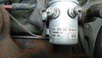
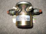
UncleSam, just so you know, I am really questioning that relay . I bought a few of these as well, and had them sitting around on the shelf for a few weeks and got around tonight to finally doing a bunch of testing.

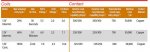
The energizing coils are extremely heavy (fewer wires, larger gauge). This makes the resistance within the coil much lower. It is hanging somewhere around 5-6 ohms. This is around half of what we found is normal for an ST85 type relay.

In effect then what is happening during tests is that the coil is drawing a much larger amount of amperage. So much so that a stock controller may not drive it.

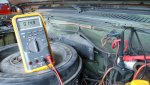
Using five different controllers, two original stock, and three prototypes here, each with a different component makeup, I tested six of the relays in question. I disassembled one.

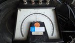
Of the six that I tested, two would not close at all, and all four of the others had a huge time delay before closing.

Worst of all, during testing of all six the transistor on the controller was severely overheating. In one case I actually did burn it out.

I am sure I can find a way to drive these relays, but it would be a re-design of the controller, not just a bit of component swapping. This would result in controllers with two different specifications (not something we find attractive).

With the large amount of these things available cheap, this frightens me a bit. I am afraid that there will be a number of casualties of both OEM and aftermarket controllers.

I have not had a chance to consult with any of the engineers on this, but frankly, right now I don’t see a way around it.

Karl, Joe and Eric thoughts?
 

UncleSam

New member
58
3
0
Location
Anniston Alabama
1stSarge, Thanks for the info, I’m new at the CUCV world, and trying to learn as I go along. I got this relay off of EBay and it suppose to be a military surplus item. I may just go and get a ST85 to be on the safe side..

Thanks,
Uncle Sam
 

doghead

4 Star General /Moderator
Staff member
Super Moderator
Steel Soldiers Supporter
26,247
1,168
113
Location
NY
The original relay coil spec is, WINDING DC RESISTANCE RATING 6.0 OHMS NOMINAL SINGLE WINDING

The -20TM says, 6-10 ohms between wires. If resistance is light blue at not correct, replace glow plug relay.

So, I would expect the GP controller should have been designed for that.

The original relays were visually like the one I used in the DH starter relay mod.

I also think most CUCVs had the original relay replaced with the metal encased cylindrical type(visually like the one posted in post# 27 ). ( I don't have any documentation on that).

Obviously, resistance matters. I'll go look at the relay on my truck(military installed) and see what it measures.

I went out and measured my relay. The coil resistance is 13.4 Ohms. My relay is a Trombetta 974-1215-010-09. It came out of military service with this relay installed. It is the metal can type relay. I have used 3 different sources of GP controller cards with no issues.


In looking up my relay I found it has had 3 different part numbers, they are 98226-6 , 98226 , 974-1215-010-09

Here is a chart from the manufacturer. My relay is the 100% duty relay.
 

Attachments

Last edited:

ChiefMinion

New member
Steel Soldiers Supporter
26
12
3
Location
Prescott, AZ
UncleSam, I apologize for taking your straightforward repair thread off into the weeds. That was not my intention. FWIW, I made the mod from Warthog step #2 last weekend. Working fine. The wire supplying the stud from the battery is not even slightly warm while the glow plugs are cycling.

In #19, I was assuming that the resistance of the resistor pack (considered as a unit) and the 8 glow plugs (considered as a unit) was roughly equal. Based on the resistance numbers from Doghead and Mistaken1, that assumption is only good if "roughly" is stretched to the breaking point. I should have taken the time to get the real numbers.

Also, my next concern is the wire size and fusible link capacity on the 12v wire that supplies the truck(when adding the GP load to it).
This was my original concern and the reason for my original question.

It is safe to say, the difference when resupplying to 12 volts is, you double the amp load on the front battery and eliminate all load on the rear battery (even though the amp load of the system is reduced slightly).
Doghead, I respectfully take issue with this statement. Using the numbers in Mistaken1's post, the load on the front battery is 73.28 amps in the 24V example. (The rear battery too.) In the 12V example, the load on the front battery is 64 amps. H.S. physics has been over 30 years ago, but I believe that the amperage in a simple circuit is the same anywhere in the circuit. (You have to treat the resistors as a single unit and the glow plugs as a single unit to have a simple circuit in this case.)

It seems that you are saying that each battery adds amperage to the equation. (Hope I'm not misstating you.) I'm saying that the amperage is determined by the total voltage and resistance in the system. Further, that each battery is contributing half the voltage at the given amperage. (Wish I could make this point with numbers. I think I could using the watts supplied and consumed by each component in the two scenarios but I'd have to work at that a bit.)

Again, using Mistaken1's post, I'm going to say that the conversion 24V to 12V as described actually lowers the amperage draw on the front battery from 73 to 64 amps. Coming full circle to my original question, I've added 64 amps of load to that 12V stud block on the fire wall that it didn't have before. Seems to work fine, but I too wouldn't add head lights or anything else significant. Maybe when I have some time, I'll add a new supply with a fusible link for the glow plugs.

All I was really trying to do is avoid the problem of cascading failure of the glow plugs if one or two start to fail by going to 12V. It seemed like a good idea.
 

antennaclimber

Moderator
Moderator
Steel Soldiers Supporter
1,353
895
113
Location
State College, PA
I made some measurements on my M1009.

The GP relay coil had a resistance of 14.9 ohms.

With 2 glow plugs connected, the current draw was about 24 amps.
With 4 glow plugs connected, the current draw was about 50 amps.
Full scale on the meter is 50 amps.
The engine was cold and was not started for testing.

My glow plugs are fed from the 12 volt side of the batteries, the resistor has been by passed.
The glow plugs are one year old AC60G's.
Karl
 

Attachments

Last edited:

UncleSam

New member
58
3
0
Location
Anniston Alabama
So, doghead you think I'm good to go with the relay I've got?


The original relay coil spec is, WINDING DC RESISTANCE RATING 6.0 OHMS NOMINAL SINGLE WINDING

The -20TM says, 6-10 ohms between wires. If resistance is light blue at not correct, replace glow plug relay.

So, I would expect the GP controller should have been designed for that.

The original relays were visually like the one I used in the DH starter relay mod.

I also think most CUCVs had the original relay replaced with the metal encased cylindrical type(visually like the one posted in post# 27 ). ( I don't have any documentation on that).

Obviously, resistance matters. I'll go look at the relay on my truck(military installed) and see what it measures.

I went out and measured my relay. The coil resistance is 13.4 Ohms. My relay is a Trombetta 974-1215-010-09. It came out of military service with this relay installed. It is the metal can type relay. I have used 3 different sources of GP controller cards with no issues.


In looking up my relay I found it has had 3 different part numbers, they are 98226-6 , 98226 , 974-1215-010-09

Here is a chart from the manufacturer. My relay is the 100% duty relay.
 

Attachments

doghead

4 Star General /Moderator
Staff member
Super Moderator
Steel Soldiers Supporter
26,247
1,168
113
Location
NY
Yes, I would try it.

Did you ever measure it's coil resistance?
 

UncleSam

New member
58
3
0
Location
Anniston Alabama
Yesterday, I measured the coil resistance and got 3.4 ohms, then


I rechecked the relay with another ohm meter this evening, and it checked 9 ohms.
 
Last edited:

UncleSam

New member
58
3
0
Location
Anniston Alabama
OK I've done the wire clean up, and ready for the next step..[thumbzup] New setup works GREAT!!!

After changing the ground wire around as you stated, my "wait" light and other dash light are working like they should...:p


So where are you on the wiring cleanup? Ready for the next to-do list?
 
Last edited:
Top
AdBlock Detected

We get it, advertisements are annoying!

Sure, ad-blocking software does a great job at blocking ads, but it also blocks useful features of our website like our supporting vendors. Their ads help keep Steel Soldiers going. Please consider disabling your ad blockers for the site. Thanks!

I've Disabled AdBlock
No Thanks