SLTRAM98
New member
- 18
- 8
- 3
- Location
- North Carolina
Looking for some help on this one. I have a MEP-007B with the Cat 3306 engine 100kw generator. Has 1000 hrs on it.
Genset background:
- Has not been running in roughly 11 years.
- Was in use when it quit, the guys I got it from had no idea what was wrong with it.
- Barn stored after it quit.
Investigation and what I know:
- The genset has a full (100%) tank of diesel in it, but the day tank and engine fuel filter housing was bone dry. Implies to me that she was running, then something failed in the fuel call system and it ran out of fuel without ever shutting down on its own. Likely the guys thought it was out of fuel, filled it up and it would not run since the priming pumps would not cycle at all.
- When you cycle the start-run-stop switch to the run position, no fuel pumps turn on. The Low Oil Pressure light comes on 'sometimes', the over speed light also comes on 'sometimes'.
- Hit the over speed reset, and light does not go out, but if you toggle start-stop-run switch off and on a few times both lights come and go depending on the speed of the wind and angle of the sun.
- If you crank the engine it will not hit.
- I cleaned all the priming pumps (x2), pulled strainer baskets, pulled filters (1 strained, 2 filters) and jumped 24vDC to A27 panel board A5, CR6 diode. Pumps come on, float works perfectly, day tank fills, life is good.
- 1) I know both pumps are good and pump great.
- 2) I know the fuel day tank solenoid is working.
- 3) I know the float system works.
- 4) I know 100% I have gravity feed pressure from the day tank to the injection pump on the engine.
- 5) I cracked injector lines, and have fuel at injectors on the head of the engine.
- 6) Crank engine and it SMOKES, like it really wants to start, but cant, with the 24vDC bypassing shutdown safety's directly connected to the fuel system I am at a loss as to why it will not start since all the safety's (I think) are jumped in order to make pumps run. I have it sucking brand new diesel out of a 5 gallon jug and clean nice fuel at the injection pump.
- 7) I have replaced diodes CR27 and CR28, I know they are working.
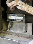
-") I opened A27 relay Mode 1 box, the A5 circuit board is in great shape, but you can see Resistor R3 has been a bit warm, slight discoloration but nothing compared to other gensets I have worked on - not sure if this helps just a note.
I opened A27 relay Mode 1 box, the A5 circuit board is in great shape, but you can see Resistor R3 has been a bit warm, slight discoloration but nothing compared to other gensets I have worked on - not sure if this helps just a note.
- Strange note: If I turn ON Battle Short, the red light comes on, and the start-run-stop switch STOPS working at all, no cranking, no anything.
- I applied 24vdc to the fuel shut off solenoid on the injection pump and it works as expected. CLARIFY to check my sanity here, the solenoid is regularly OPEN, meaning NO voltage. Voltage applied means the solenoid activates and shuts down the engine, correct? EG if I apply 24vdc to the solenoid while cranking it has no fuel and will never start.
- Engine speed sensor - I ran it all the way in until it bottomed out on the flywheel, then backed it out 3/4 of a turn. Not sure how else to check this item. I read on a different thread to look for 10.5volts from this however, not sure where to actually check for that voltage.
- I applied 24vDC to K1 relay TB posts 8 on board A4 and this activities the fuel shut off solenoid and runs the priming pumps.
I have TM -12, -24 and luckily found -34 for this unit. Still after all day working on her, not sure what I am missing.
How does the speed governor control this engine is a question; since the engine smokes like its got loads of fuel, it seems something is keeping it from starting, however, its not a smart engine (no computers) so how is the Speed Governor actually wired/connected to the engine? Since the Over Speed light is on sometimes, I have a feeling something is a-miss in that department. I think Oil Pressure light is only on because the engine is off, if you crank it for a few seconds light seems to disappear for a bit then comes again. Also, any way to bypass speed governor to check it quickly?
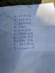
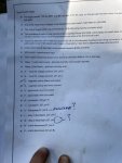
I have attached the wire diagram to this thread. Circles are where I tested 24Vdc, yellow highlighted madness is where I 'think' I traced power routing. Square boxes are denoting some (not all) of the relays, boards, switches.
Let me know what you think guys, all ears and can get pictures. Thank you
Genset background:
- Has not been running in roughly 11 years.
- Was in use when it quit, the guys I got it from had no idea what was wrong with it.
- Barn stored after it quit.
Investigation and what I know:
- The genset has a full (100%) tank of diesel in it, but the day tank and engine fuel filter housing was bone dry. Implies to me that she was running, then something failed in the fuel call system and it ran out of fuel without ever shutting down on its own. Likely the guys thought it was out of fuel, filled it up and it would not run since the priming pumps would not cycle at all.
- When you cycle the start-run-stop switch to the run position, no fuel pumps turn on. The Low Oil Pressure light comes on 'sometimes', the over speed light also comes on 'sometimes'.
- Hit the over speed reset, and light does not go out, but if you toggle start-stop-run switch off and on a few times both lights come and go depending on the speed of the wind and angle of the sun.
- If you crank the engine it will not hit.
- I cleaned all the priming pumps (x2), pulled strainer baskets, pulled filters (1 strained, 2 filters) and jumped 24vDC to A27 panel board A5, CR6 diode. Pumps come on, float works perfectly, day tank fills, life is good.
- 1) I know both pumps are good and pump great.
- 2) I know the fuel day tank solenoid is working.
- 3) I know the float system works.
- 4) I know 100% I have gravity feed pressure from the day tank to the injection pump on the engine.
- 5) I cracked injector lines, and have fuel at injectors on the head of the engine.
- 6) Crank engine and it SMOKES, like it really wants to start, but cant, with the 24vDC bypassing shutdown safety's directly connected to the fuel system I am at a loss as to why it will not start since all the safety's (I think) are jumped in order to make pumps run. I have it sucking brand new diesel out of a 5 gallon jug and clean nice fuel at the injection pump.
- 7) I have replaced diodes CR27 and CR28, I know they are working.
-
- Strange note: If I turn ON Battle Short, the red light comes on, and the start-run-stop switch STOPS working at all, no cranking, no anything.
- I applied 24vdc to the fuel shut off solenoid on the injection pump and it works as expected. CLARIFY to check my sanity here, the solenoid is regularly OPEN, meaning NO voltage. Voltage applied means the solenoid activates and shuts down the engine, correct? EG if I apply 24vdc to the solenoid while cranking it has no fuel and will never start.
- Engine speed sensor - I ran it all the way in until it bottomed out on the flywheel, then backed it out 3/4 of a turn. Not sure how else to check this item. I read on a different thread to look for 10.5volts from this however, not sure where to actually check for that voltage.
- I applied 24vDC to K1 relay TB posts 8 on board A4 and this activities the fuel shut off solenoid and runs the priming pumps.
I have TM -12, -24 and luckily found -34 for this unit. Still after all day working on her, not sure what I am missing.
How does the speed governor control this engine is a question; since the engine smokes like its got loads of fuel, it seems something is keeping it from starting, however, its not a smart engine (no computers) so how is the Speed Governor actually wired/connected to the engine? Since the Over Speed light is on sometimes, I have a feeling something is a-miss in that department. I think Oil Pressure light is only on because the engine is off, if you crank it for a few seconds light seems to disappear for a bit then comes again. Also, any way to bypass speed governor to check it quickly?
I have attached the wire diagram to this thread. Circles are where I tested 24Vdc, yellow highlighted madness is where I 'think' I traced power routing. Square boxes are denoting some (not all) of the relays, boards, switches.
Let me know what you think guys, all ears and can get pictures. Thank you
Attachments
-
722.6 KB Views: 3


![IMG_1770[1].JPG](/data/attachments/675/675765-77572e8361ee9b6fecdfeb9ceca8223b.jpg)
![IMG_1780[1].JPG](/data/attachments/675/675766-2c6b4ee4021df21b6bd1b5e45d03feab.jpg)
![IMG_1938[1].JPG](/data/attachments/675/675770-39e958545ef31123f3d1daffcc8665d2.jpg)
![IMG_1937[1].JPG](/data/attachments/675/675771-ba892498dcb2f98ed0687b8d504e5a32.jpg)