• Steel Soldiers now has a few new forums, read more about it at: New Munitions Forums!

  • Microsoft MSN, Live, Hotmail, Outlook email users may not be receiving emails. We are working to resolve this issue. Please add support@steelsoldiers.com to your trusted contacts.


multifuel fuel pump hydraulic head removel

maxspeed250

New member
18
1
0
Location
Hamlin, NY.
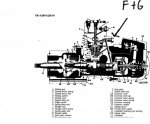
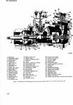
Doghead is most correct, as is Gimpyrobb. Not sure about m-35tom, Herr Bauer and I don't quite speak the same lingo. ;) Thank you all for schooling me on the scalloped washer. Heck, I said I wasn't a injector pump expert. Nobody enjoys admitting they erred and I'm no different. But it wasn't the first time and most certainly won't be the last. And we all learned something, didn't we? Evidently, I got lucky as you have 2 chances for the scalloped thrust washer on the quill shaft to line up with every rotation of the 30 tooth HH driven gear. So my HH must have been about 180 degrees out phase of scribed red painted tooth alignment. Gimpyrobb brings up an interesting point by stating he has had some hydraulic heads that will not pull out with the tooth aligned. Betcha someone had those pumps apart at some point and didn't install the quill shaft correctly indexed. The clearance cut in the thrust washer could be anywhere in relation to the witness tooth on the driven gear, so the procedure I outlined could have merit for those situations where a HH swap needed to be done on a incorrectly assembled pump quill drive. You would still need to keep rotating the engine a small amount and attempting to pull the HH up, as soon as you could tell it will pull free of the scalloped thrust washer, you would reseat the HH and paint a new witness mark on the driven gear. Or just keep lining everything up like Cranetruck and the TM suggest!
 

m-35tom

Well-known member
Supporting Vendor
3,021
221
63
Location
eldersburg maryland
the timing pointer in the window does not even come close to lining up when the HH is propper position to be removed. it is only for crankshaft timing. so at best you would just be guessing. if the red scribed gear is used there is no error at all. granted some trucks may have been put togeather wrong, but even this is easily corrected.
tom
 
Last edited:

doghead

4 Star General /Moderator
Staff member
Super Moderator
Steel Soldiers Supporter
26,247
1,168
113
Location
NY
Tom, in post#20, I highlighted in green, the line and the pointer(in the position where the HH can be removed). Any marks be used ,if you know where they need to be.(only where the line is, as the pointer is not used they way I just explained it.)

Since it's all driven by gears that are set(timed), everything has a relative position.
 

m-35tom

Well-known member
Supporting Vendor
3,021
221
63
Location
eldersburg maryland
yes, i get that. but since the designer was thoughtful enough to put a mark on the HH gear, why even take the pointer cover off?? by the way, the reason that the red tooth is used is so that the cam for the HH piston will be at the lowest point, making it easiest to reinstall the head. this is why it does not correspond to the other timing marks.
 

doghead

4 Star General /Moderator
Staff member
Super Moderator
Steel Soldiers Supporter
26,247
1,168
113
Location
NY
Doghead
In the first 2 pictures, you can clearly see the thin metal "plate" on top of the gear that drives the HH. It has a half round cutout in it that will only allow the HH to lift out in one position. To properly position the HH for removal, you need to look inside the shutoff rod cover, to index the "cut out" in the correct position(as indicated by the painted tooth and pointer).

Tom
don't see how doghead is correct at all.

Tom
yes, i get that. but since the designer was thoughtful enough to put a mark on the HH gear, why even take the pointer cover off?? by the way, the reason that the red tooth is used is so that the cam for the HH piston will be at the lowest point, making it easiest to reinstall the head.
I am wrong,and yet you posted the same thing as I did. :?


What would a guy do if, the painted mark is Missing? Hmm, there are alternatives, and since I posted them, now they will know!

And before you tell me that in 40 years of HH replacements, you have never seen that. I had a call recently, asking what to do, because there was NO painted mark! My suggestion(same info I posted above) worked and they successfully removed and replaced the HH with no damage or difficulty.


btw, I had posted this also, if you missed it the first time
Again, this is not how the TM says to do it and it is not the best option, but it is possible if you know what your looking at.
And Lastly, I am done discussing any of this here. I suggest if anyone needs further info, contact Tom.
 
Last edited:

m-35tom

Well-known member
Supporting Vendor
3,021
221
63
Location
eldersburg maryland
DH, yes you are correct. i was not in full agreement about using the timing window since most people on here doing this need the simplest version and may not fully understand the position relations in the pump. however, while i will say yes i have seen many with no red paint left on the tooth, i have never seen a tooth with no scribed line. yes it may be very hard to see and in this case using the timing mark to help locate it may help. but the timing mark comes up twice for each rotation of the HH so if it is not found the first time the engine may have to be rotated another revolution.

tom
 

AndrewH

Member
376
1
18
Location
Boyne City MI
My my my, what have I restarted? :???: Ok people, I am not the expert here at all. Thats why I asked the question. I can tell you as a fact when the hydraulic head came off of the pump, not one of the marks really lined up. I had everything set so the pointer under the cover on the timing assembly lined up and the red painted tooth on the hh lined up. It would lift just enough to say it was loose. An SS member who has done a few of these was able to talk me thru the process and knew that some of the pumps need a little extra attention. I had to move the pump back about a "tooth" as seen in the hh on the painted tooth and then was able to lift it out when the HH drive gear cap piece's window was aligned to release the HH. So everybody relax and grab a beer. :beer: Or do I need to go take pictures?
 

Floridianson

Well-known member
Steel Soldiers Supporter
7,391
2,438
113
Location
Interlachen Fl.
OK sounds like everybody is on the same page so I thought I would post the instructions from AMBAC. Just picked up a nice little supply of the heads from GL. If you have trouble reading them just hit me with a E mail and I can E you back with a better copy.
 

Attachments

Last edited:

Floridianson

Well-known member
Steel Soldiers Supporter
7,391
2,438
113
Location
Interlachen Fl.
Also as per the instructions you maybe replacing a hyd. head with lube duct and filter arrangement with a non lube duct hyd. head. You will need the special screw and plug to compleat the install.
Here I think they are talking about the F and G pumps. On the digram I posted you can see the oil line with the screw and filter F and G. Sounds like you remove the screw and filter and plug off this passage. The outher is the pump without the upper oil line. I am still reading so any comments will be usefull.
 

Attachments

txbronco

New member
3
0
0
Location
south texas
I had to change out my HH shaft key/shear key
was broken. When installing the new head the red/scribe tooth would only reinstall by one tooth past the red mark. Will this work or is the timing going to be off. Could it be excess play because of the broken shear(old head) causing the one tooth off on the new head?
 
Last edited:

Floridianson

Well-known member
Steel Soldiers Supporter
7,391
2,438
113
Location
Interlachen Fl.
No nothing broke/wore out correct proper timing is all marks on the money ( balancer & 4 bolt advanced window) and the Head will be one tooth to the rear. We only remove the Head when Head alinement mark is on the money but the other two would be off then. So sounds like you are good to go.
 
Last edited:

rustystud

Well-known member
9,071
2,388
113
Location
Woodinville, Washington
Since the red mark is when the piston is at top dead center it naturally wants to move ahead due to the spring pressure. Since there isn't a solid coupling from the engine (the advance unit is controlled by three springs) the piston spring can and will push the cam downward. That is why the TM instructions allow it to be a half a tooth advanced past the red mark.
 
Top
AdBlock Detected

We get it, advertisements are annoying!

Sure, ad-blocking software does a great job at blocking ads, but it also blocks useful features of our website like our supporting vendors. Their ads help keep Steel Soldiers going. Please consider disabling your ad blockers for the site. Thanks!

I've Disabled AdBlock
No Thanks