• Steel Soldiers now has a few new forums, read more about it at: New Munitions Forums!

  • Microsoft MSN, Live, Hotmail, Outlook email users may not be receiving emails. We are working to resolve this issue. Please add support@steelsoldiers.com to your trusted contacts.

Picked up 6 MEP-802A gensets and will be documenting making them all runners here

pclausen

Well-known member
Steel Soldiers Supporter
452
281
63
Location
Afton, VA
Good point Guy. You're right, it could have shaken a LOT worse and by the 2nd clip, it was actually relatively smooth.

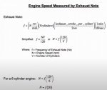
I ran a spectrum analyzer on the 2nd clip and I picked up an exhaust frequency of about 47 Hz.

So using this formula:

N = f (120/V)

Where N is RPM, f is frequency and V is the number of cylinders, I can estimate the RPM was about 47 x 60 = 2,820 rpm. So yeah, a little on the high side. :)

I might not have picked the right fundamental, or lowest major tone, but with the crappy free app I downloaded on my phone and then played back the clip in my computer, that was the lowest one it could detect.

This is where I got the formula from:

rpm_from_exhaust_hz.jpg
 
Last edited:

Ray70

Well-known member
2,552
5,759
113
Location
West greenwich/RI
Here's my take on things....
In the first video I believe it is running on 1 cylinder. It is taking far too long for it to come up to speed and the smoke puffs look like a single cylinder firing not 2, and speed sounds fairly close to 1800.
In the 2nd video it sounds smoother, but I still think you may only have 1 cylinder firing, and it sounds like it is too slow, sounds like 1500 RPM or less.
The engine speed does not sound too fast to me, there is no way that was 2800 RPM's
Those motors have a hard time idling lower than 1200 and won't rev much past 2200, and at 2200 you know it is too high!
Not sure if you checked for power or not, but if you have power, a $25 Kill-a-watt meter will tell you Hz.
I would remove the exhaust manifold, start it up and feel the exhaust from each cylinder to see if both are hot or one is cold.
You will know immediately with no question if both cylinders are firing.
This also lets you see which cylinder is smoking, if smoke doesn't clear almost immediately.
You can use your IR thermometer, but it takes a little while to get hot and on a 2 cyl. the heat travels quickly and may be misleading.
Another quick trick is to crack the injector line on one of the cylinders at a time.
If no change in engine speed is noticed, that cylinder was not firing.
If you crack a line and the engine dies, the OTHER cylinder is probably a dud...
 

pclausen

Well-known member
Steel Soldiers Supporter
452
281
63
Location
Afton, VA
Thanks Ray. Great tips. If it is indeed only firing on one cylinder, that would make the RPMs just over 1,400, which would be consistent with what your trained ear is telling you. I had the throttle/frequency adjustment pretty close to the lowest setting in that 2nd video.

I'll pull it out of the garage tomorrow and crack each injector line to see if I am only firing on one cylinder or not. I know the head has been done on this 2006 engine, and I'm about 75% sure I did put new rings on it as well back in 2014/2015 before putting it away. It also has brand new injectors.

When I crack the injection lines, I'll see if I get fuel coming out of both IPs.
 

pclausen

Well-known member
Steel Soldiers Supporter
452
281
63
Location
Afton, VA
So today didn't quite go the way I had planned. Early this morning, around 5am, I left the house and drove up to MD, North of Baltimore, to look at a 2000 802A. It supposedly ran, but was not making power. About half way there, around the time I entered MD, I started to feel a little bit of a wobble. Not in the steering wheel interestingly enough. I was making good time and had hardly any traffic, so I slowed down a bit and got through the tunnel and was about 15 miles from my exit on I95 when the wobble got a lot worse. So I started limping along in the emergency lane trying to make it to the next exit as I really didn't want to be stranded on I95. Well, after about a mile it got really bad and I had to pull over.

Popped the left front hub cap, everything was good. Popped the right front, and this is what I found:
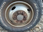
IMG_0518.JPG

So 5 studs had broken off and the lug nuts on the last 3 were very loose. So needless to say, I could not continue and I was about 3 hours from home. So I called Mike, the guy that had the 802 I was going to look at and he was really cool and threw some tools in his truck and headed my way. We agreed that working on the truck on the side of I95 was not ideal, so I called AAA to have them come and flatbed the truck to his place.

I very happy I didn't loose the wheel in the tunnel that was about 10 miles before this. That would have been a real mess, even at 7:30 am on a Saturday.

After Mike picked me up, and we headed to the auto parts store to pick up 8 new studs and 8 new lug nuts. Once we got the parts, we hang out at his place waiting for the tow truck to show. He had a bunch of military trailers, including a large communications one, which was insulated and way cool. He used it for camping.

About 20 minutes later, the tow truck showed up with my poor truck on the back:

IMG_0519.JPG

Popped the wheel off, and knocked out the studs:
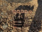
IMG_0521.JPG

New studs installed and wheel back on:
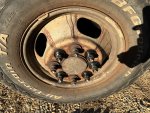
IMG_0520.JPG

The really nice thing about a dually is that there is an extender on the front hub that makes replacing the studs real easy with no need to remove the brake caliper or anything.

Once the truck was back on the road, we headed over to his other property, which is where the generator was. Since it was now much later in the day, and given all the help he had provided, the only thing I checked was that the quad windings were good. They were and measured around around 1.1 ohm. The reason I was concerned about the quad winding, was that this unit did not have the fuse mod and he started it up about 3 weeks ago before posting it for sale. It ran fine, but was not making power. He had it sitting for about 2 years. When he ran it back then, it DID make power.

So we load the generator on my truck and I head back home. Made it back safely with no further incidents.

Unit is nice and clean and all panels are straight:
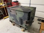
IMG_0524.JPG

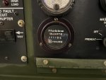
Only has 32 hours on it:

IMG_0523.JPG

Inside looks brand new, but no fuse mod:
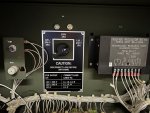
IMG_0533.JPG

It looks like it was reset back in November 2015:
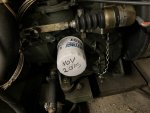
IMG_0525.JPG

And:

IMG_0526.JPG

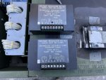
Are the above filters what they used when resetting these machines?

If so, why would they not have done the fuse mod during the reset in 2015?

Needless to say, I didn't get a chance to play with the 2007 that is seemingly only firing on one can.

Tomorrow I have most day to fiddle with the 2007 and this newly acquired 2000 with 32 hours on it after the reset. I picked it up for $900, which I think was decent, assuming it won't take much to get it to make power and it otherwise being a really clean unit with only 32 hours on it.
 
Last edited:

pclausen

Well-known member
Steel Soldiers Supporter
452
281
63
Location
Afton, VA
It does NOT have a data plate indicating it was resent. Of all my 802 units, only one has such a plate, yet they all have the fuse mod except for the 2008 one with the cracked piston.

Updated table showing current status of each set:

UnitAcquire DateBuild DateHoursCostEngine ID TagInitial ConditionMain Work CompletedNew partsCurrent ConditionStill to be done
MEP 802A #106/201407 20063544$40044020385DN2WA72Water in boresHead rebuildInjectors
Rings
rubber mount
rear bearing
Water Pump
Engine runs roughTroubleshoot engine
MEP 802A #206/201406 20071355$60044006095DN2WA72Water in boresHead rebuildInjectorsNo compressionNew rings and hone
MEP 802A #306/201408 20092844$1,000081028765DB2WA72Water in boresHead rebuild
Block hot tanked
Injectors
Rings
rear bearing
CompleteLoad test
MEP 802A #410/201407 20093504$1,200081028775DN2WA72Engine cranks
Cracked rear bell housing
Makes powerFix bell housing, Load test
MEP 802A #510/201408 20087502$800081019635DN2WA72Cracked piston
Fuel tank drilled
In piecesAssemble
MEP 803A #101/202107 20005717$5,0000006800210DN4WA72Makes powerReplaced cracked gaugesCompleteFuse Mod, load test
MEP 802A #602/202206/200032$900000718555DN2WA72TBDTBDFuse Mod, load test

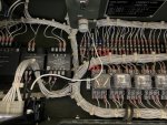
On this newly acquired set, I noticed these 2 wires not being zip tied in with the rest:

IMG_0535.JPG

They both go to the fault indicator panel. The interesting thing is that all my other 802 sets have those same two wires, including one of them being black, but they are all zip tied in with the rest of the harness, but it is clear they were added after the fact on all the sets.
 

pclausen

Well-known member
Steel Soldiers Supporter
452
281
63
Location
Afton, VA
Took the newly aquired 2000 unit with 32 hours on it outside this morning and drained the old fuel. It smelled pretty nasty.

IMG_0538.JPG

After filling with fresh fuel and priming for about 5 minutes, I attempted to start it:


So pretty rough at first, which was to be expected. It was also below freezing at around 25F.

After running for about 10 minutes I shut her down and put a couple of bolts in the front top piece that was rattling and the started it up again. Much quieter and the smoke was completely gone:


At this point I checked the voltage output and I'm getting right around 68V between phases and half that between any phase and ground. I get the proper voltage when I hold S1 in the start position. I did install the fuse mod on this unit last night. Checked again just now after running the set per the above, and the fuse is blown but the quad windings still measure 1.2 ohm on the leads by pins 7 and 8 on A1.

So it looks like A1 is bad. Since this set was previously run without the fuse mod, how can it be that the quad windings didn't fail when running without the fuse mod? Or perhaps there are other scenarios that will take out A1 and not kill the quad windings?
 
Last edited:

Guyfang

Moderator
Staff member
Moderator
16,627
23,753
113
Location
Burgkunstadt, Germany
It does NOT have a data plate indicating it was resent. Of all my 802 units, only one has such a plate, yet they all have the fuse mod except for the 2008 one with the cracked piston.

Updated table showing current status of each set:

UnitAcquire DateBuild DateHoursCostEngine ID TagInitial ConditionMain Work CompletedNew partsCurrent ConditionStill to be done
MEP 802A #106/201407 20063544$40044020385DN2WA72Water in boresHead rebuildInjectors
Rings
rubber mount
rear bearing
Water Pump
Engine runs roughTroubleshoot engine
MEP 802A #206/201406 20071355$60044006095DN2WA72Water in boresHead rebuildInjectorsNo compressionNew rings and hone
MEP 802A #306/201408 20092844$1,000081028765DB2WA72Water in boresHead rebuild
Block hot tanked
Injectors
Rings
rear bearing
CompleteLoad test
MEP 802A #410/201407 20093504$1,200081028775DN2WA72Engine cranks
Cracked rear bell housing
Makes powerFix bell housing, Load test
MEP 802A #510/201408 20087502$800081019635DN2WA72Cracked piston
Fuel tank drilled
In piecesAssemble
MEP 803A #101/202107 20005717$5,0000006800210DN4WA72Makes powerReplaced cracked gaugesCompleteFuse Mod, load test
MEP 802A #602/202206/200032$900000718555DN2WA72TBDTBDFuse Mod, load test

On this newly acquired set, I noticed these 2 wires not being zip tied in with the rest:

View attachment 859494

They both go to the fault indicator panel. (They should. That's the way they came, from the factory. Zip tied in the harness.) The interesting thing is that all my other 802 sets have those same two wires, including one of them being black, but they are all zip tied in with the rest of the harness, but it is clear they were added after the fact on all the sets. (No. See above. The reason they are not in the harness, is because they were changed. And someone was lazy. For a while, we had max problems with the GFI. It was a high use item. And that's where the wires go. To the GFI, not the A2, (Fault indicator) . The GFI gets screwed to the A2 panel, but is NOT a part of it. In fact, if you ever see an old set, with the original GFI, it will have an inline fuse on the black wire.


It does NOT have a data plate indicating it was resent. No data plate, no reset.


So it looks like A1 is bad. Since this set was previously run without the fuse mod, how can it be that the quad windings didn't fail when running without the fuse mod? Or perhaps there are other scenarios that will take out A1 and not kill the quad windings?

You are assuming. Test the A1, then call it bad. probably is, but TEST, TEST, TEST.

So
, how can it be that the quad windings didn't fail when running without the fuse mod? Could be, someone needed a good A1, and swapped it out before you got it. Or the A1 had a failure that was NOT over voltage.

Open to see comments.
 

kloppk

Well-known member
Steel Soldiers Supporter
2,126
3,490
113
Location
Pepperell, Massachusetts
...At this point I checked the voltage output and I'm getting right around 68V between phases and half that between any phase and ground. I get the proper voltage when I hold S1 in the start position. I did install the fuse mod on this unit last night. Checked again just now after running the set per the above, and the fuse is blown but the quad windings still measure 1.2 ohm on the leads by pins 7 and 8 on A1.

So it looks like A1 is bad. Since this set was previously run without the fuse mod, how can it be that the quad windings didn't fail when running without the fuse mod? Or perhaps there are other scenarios that will take out A1 and not kill the quad windings?
Proper voltage with S1 in START is a good sign.

To see if the Quad winding is putting the proper voltage measure the AC voltage across A1 terminals 7 & 8 when S1 is in START while it's running. YOu should get approx 69 volts AC there. If so the Quad windings are working.
Also measure across A1 terminals 3 & 4 with S1 in START. You should measure approx 120 VAC there.

The A1 can fail without damaging the Quad winding. What kills the Quad winding is if the diode bridge inside A1 shorts out which in turn shorts out the output of the Quad winding causing the Quad to burn out. The Fuse Mod is to prevent the Quad winding from burning up if the A1 diode bridge shorts out.
Sounds like somehting els may have failed in the A1 causing the low voltage.
From your initial info it would appear that A1 is bad assuming you get the 69 volts AC as described above.

There is a procedure to test the A1 in the -24 TM.
 
Last edited:

pclausen

Well-known member
Steel Soldiers Supporter
452
281
63
Location
Afton, VA
Yep, A1 had failed in a matter that did not take the quad windings with it, or it was swapped out at some point as Guy pointed out. Thanks for the detailed description of the A1 failure scenarios Kurt! Interesting that this set only has 32 hours on it, is a 2000 model, and was never reset.

So I swapped in the A1 from my spare:

IMG_0546.JPG

And it started making power. The voltage was below 240V (about 230V or so) with the pot all the way to the right. So I adjusted the RANGE ADJUST on A1 to increase the range (had to turn it LEFT instead of RIGHT to INCREASE range). And I was then easily able to adjust to get 240V.

I then took unit down to the shop for some load testing. After letting it warm up for a bit, I started out at around 5,500 watts. Interestingly enough, the PERCENT RATED POWER meter was only showing about 80% when doing so. I then kicked it up a notch to 6,200 watts and the power meter was indicating a little less than 100%. I think I can fix that by adjusting the meter with a small flat blade screwdriver. There was some smoke under load, but I think that is to be expected when taxing the engine? It might get better after running with a load for a longer period of time.


While it was still running with a load, I noticed a pretty healthy leak from the return line:


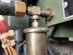
That will be easy to fix. I also noticed what appear to be a leak at a fitting for the oil sending unit:

IMG_0553.JPG

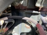
But then I discovered this on the alternator side:

IMG_0550.JPG

So I have what appears to be a coolant leak from the head gasket... I guess the head has to come off to determine exactly what's going on. That discovery kind of took the winds out of the sail a little bit with regards to this set. But overall I'm pretty pleased with how it performs, but I suspect it will need a new head gasket.

I then turned my attention to the 2007 unit that only fires on one cylinder. I loosened the high pressure line at IP #1 and it immediately started stalling, so I snug it back up.

I then went to loosen #2 and discovered that the larger nut right below it was turning as well. Shut down the set and held the larger nut with a 3/4" wrench while loosening the smaller 16mm nut for the fuel line. I then tightened the 3/4" nut really good. With the 16mm nut still loose, and loosened the hold down clamp nut just enough to where I could rotate the entire IP clockwise until I felt resistance. I then snug up the hold down clamp nut and the 16mm nut for the fuel line.

I then cranked her up:


Much better! Or so I thought. I cranked it again, and now I was back to just #1 firing:


Repeated the procedure outlined above and got the same result. Fired on both cylinders after making the adjust, and was then back to just 1 can on subsequent starts.

That's it for today.
 
Last edited:

Guyfang

Moderator
Staff member
Moderator
16,627
23,753
113
Location
Burgkunstadt, Germany
Yep, A1 had failed in a matter that did not take the quad windings with it, or it was swapped out at some point as Guy pointed out. Interesting that this set only has 32 hours on it, is a 2000 model, and was never reset.

There is a Reset document in the TM forum. But you need to understand what Reset is. Reset is to take older, or much used gen sets and return them to Tip, Top shape. What we called 10/20 Standards. A gen set is only supposed to be sent to Reset when id had a certain amount of hours, and other criteria. Red the reset document if you really want to know.

One reason it never hit reset is that it never got issued. Or was issued to a unit that never needed it. Could also have been reset back in the day. Back in the early days, the reset tag was a plastic POC that was simply pasted on the side of the gen set. You all place way too much emphasis, (Hope) on Reset. At times it was less then spotty. At times, super. But what all of you fail to understand, or better said, Know, is that Reset was more or less a guideline. At first anyway. After 2010, when I stopped contracting, I can not speak with knowledge. But it was a guideline. Some things listed in the Reset document were to be done on a, AS NEED BE basis. "If it aint broke, it dont get fixed". Often, if a part was supposed to be changed, say the TTM, (Time Totaling Meter), and the supply system did not have them, or was not able to supply them in time, the set was kicked out of shop. It was recorded as finished, with the following exceptions. And a list was provided. That list promptly went into the trash can. Who cares? works? Great. End of story. Reset is not the Holy Grail.
 

DieselAddict

Well-known member
Steel Soldiers Supporter
2,530
2,054
113
Location
Efland, NC
I then took unit down to the shop for some load testing. After letting it warm up for a bit, I started out at around 5,500 watts. Interestingly enough, the PERCENT RATED POWER meter was only showing about 80% when doing so. I then kicked it up a notch to 6,200 watts and the power meter was indicating a little less than 100%. I think I can fix that by adjusting the meter with a small flat blade screwdriver. There was some smoke under load, but I think that is to be expected when taxing the engine? It might get better after running with a load for a longer period of time.
That is normal behavior. The load meter is calibrated with a power factor of 0.8. It will read low when loaded with a resistive load.
 

pclausen

Well-known member
Steel Soldiers Supporter
452
281
63
Location
Afton, VA
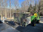
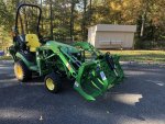
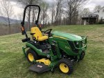
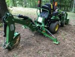
That's a John Deere 1025R with a 120R loader and 260B backhoe. Great little tractor. It is borderline able to move a 802A around however. Max it can raise it is a little over 2 feet. But given that this little tractor only weigh about 1,450 lbs. by itself, that's to be expected.

In addition to the pallet forks and bucket, I also have a grapple for the front:

IMG_2866.JPG

And a mid-mount 60" drive on drive off deck:

1025R_30.JPG

Also picked up a 6" trenching bucket and a thumb for it:

IMG_2385.JPG
It is powered by a 1.3 liter 3 cylinder Yanmar engine. I changed out the stock 6 gpm hydraulic pump with one that does 9.5 gpm. Backhoe works much better with that mod.
 

DieselAddict

Well-known member
Steel Soldiers Supporter
2,530
2,054
113
Location
Efland, NC
Nice! I’m looking at either a 2038r or a 3039r. Right now I have a 4200 but I need a loader and haven’t been able to fine one to fit it.
 

Ray70

Well-known member
2,552
5,759
113
Location
West greenwich/RI
I've got to show my son that grapple! He took an old 425 last year and outfitted it with an LPW2 engine.
Converted it to 24V and has more lights and flashers on it than most emergency vehicles!
He made forks, a weight block and a 2 stage trailer hitch for the 3 point, then he made a hydraulic plow for the front.
Right now he is welding up a home made hydraulic quick attachment and a grapple for the front.
Hopefully his pistons and hoses will be here this week.
He originally did this all at age 11. Now he's 12 and expects dad to finance his grapple then digging bucket projects..... and every day he's on-line looking at AG tread tires for it!
 

pclausen

Well-known member
Steel Soldiers Supporter
452
281
63
Location
Afton, VA
Those are nice machines! I had a 4700 that I got back in 2000 that served me well for 12 years. Then in 2012, I got a 5085M when I started clearing land and logging trees. But it was way too big for stuff around the house and moving things around near and in the shop. I got the 1025R last year (meter just went past 50 hours this weekend), and it has been great for all kinds of stuff around the house and doesn't tear up the grass. I really like the Radial tires, which are a cross between a turf tire and a R4. If I could have only one machine, I would probably get a 3 series today.
 
Top